Creation of Ribs & Screw Boss Feature
Aim: To create the Ribs and Screw Boss for the Drill Handle considering the design rules.
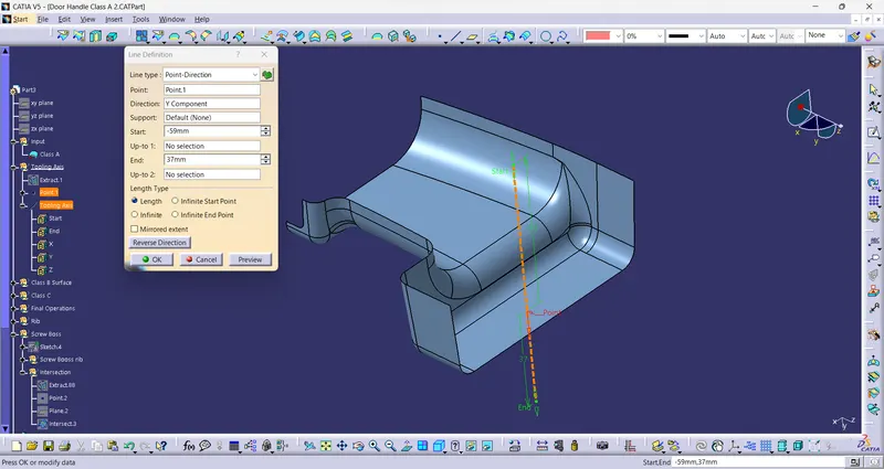
Creation of Tooling axis:
Tooling axis shows the direction in which mold moves. To define a tooling axis, firstly need to find a view/direction in ehich complete class A surface is visible (along with the side parallel to diirection).
So, for this given surface of drill handle, tooling axis can be formed in Y direction.
find a flat face and take a point on the surface and created a line with help of point and direction.
This line is the Tooling axis for the given Class A Surface.
To Convert the given Class A into Solid model, Class B and Class C surface need be created.
Class B surface:
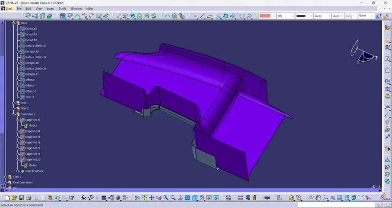
To create the Class A surface, Extrac all the flat surfaces and untrim all of them.
Extrapolate all for some instance and trimmed the unnecessary surfaces.
Here is the final B surface.
Creation of Class C surface:
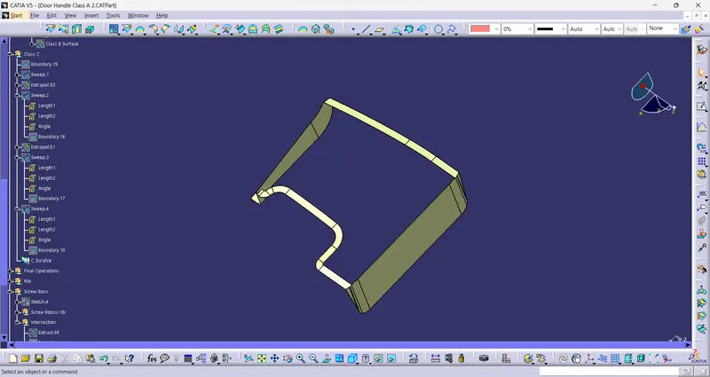
Create a boundary of class A surface.
Using sweep command extrude it. For this surafce, C surafces are in the direction of tooling axis, so using draft with direction option under line sweep, created the c surface using tooling axis as draft direction.
and for the remaining two side, use with reference surfaces option with 90 degree angle.
Cretaion of Solid model:
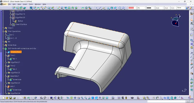
Class A and Class C surfaces joinde tgether using Joi command and the output is trimmed with the b surface.
Then using Close Surface option form part workbench, solid model is created.
Ribs:
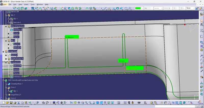
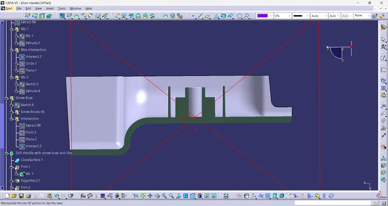
Ribs are the thin perpendicular extension from the walls or the surfaces. It provides additional support and strength to the component.
Creation of Ribs:
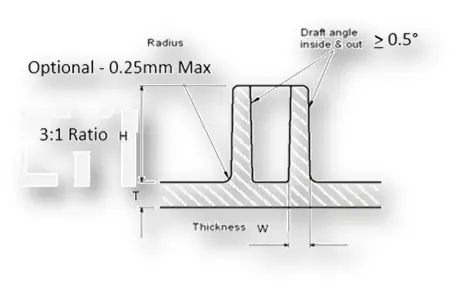
Some Major Design Rules
t = Wall Thickness of Component
Min. Draft Angle = 0.5 degree
Rib Fillet radius = 0.25 mm
Rib Thickness at base = 0.4*t
Min. Rib thickenss at top = 0.75 mm
Rib Height = 5*t
Screw Boss:
Screw bosses are small cylindrical elements for screw fitting. It helps in the assempbly of components.
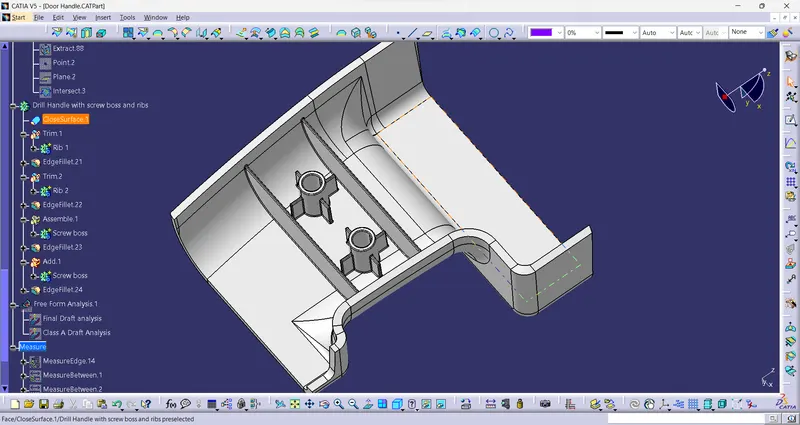
Creation of Screw Boss:
Design Rules ffor
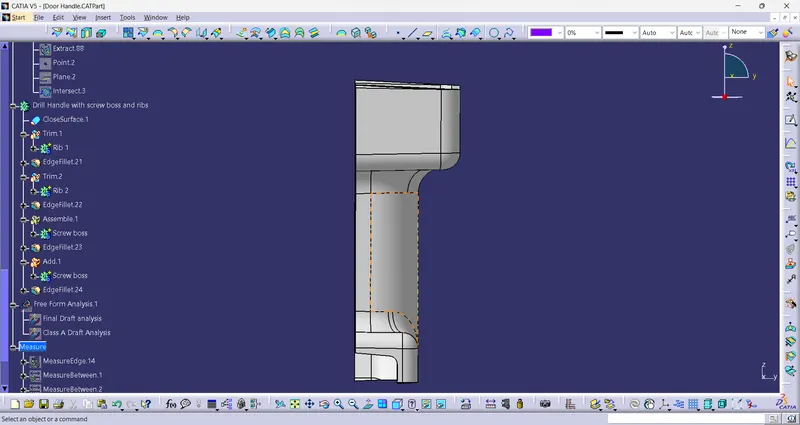
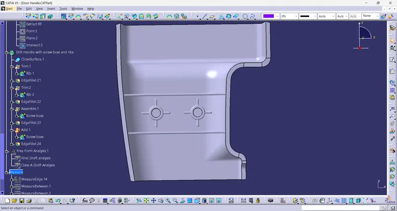
Drill handle with ribs and Screw bosses:
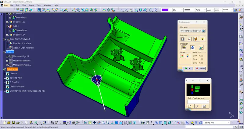
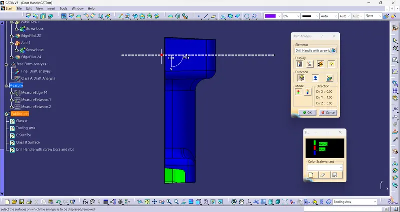
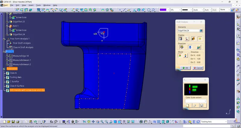
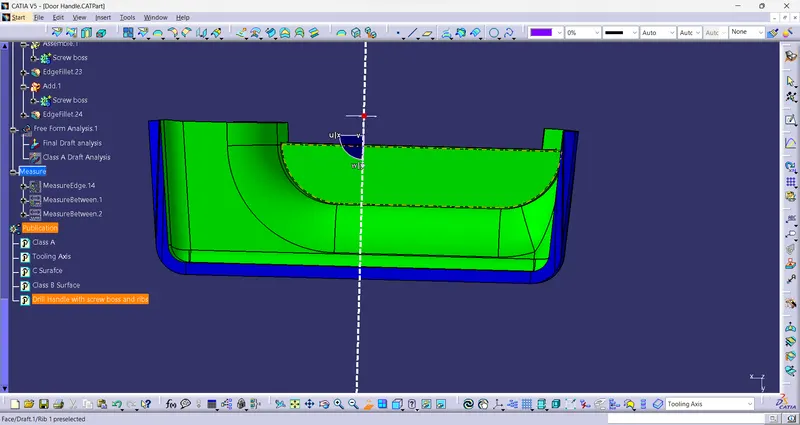
Draft Analysis of Drill Handle:
Draft analysis is a method to check whether the component is easy to eject from the molds or not. It also helps to cross verify created tooling axis.
in this green colour indicates that the draft angle is more than 0.45 degree, blue indicates 0 degree draftand red indicates below zero degree draft.
Conclusion:
Successfully created a solid model with ribs and screw bosses as per design rules from given class A surface and performed a draft analysis.