Week 9 - Challenge 1 - Base Bracket Design
AIM:
To Create the Base Bracket Plastic component through the given Class-A surface
INTRODUCTION:
- CLASS A SURFACE:
Class A is the surface created by concept sketches done by free hand sketches. The finished sketch is then transferred to a computer, and the 2D surface is created using software such as Alias. This computerized design is known as a Class A surface.
- CLASS B SURFACE:
Class B is a reference surface created by the design engineer and is a copy of the Class A surface at a distance equal to the part thickness.
- CLASS C SURFACE:
Class C is again a reference surface created by the design engineer to connect Class A and Class B surfaces, also known as the side walls of the surface.
- Given Class A surface were mention below:
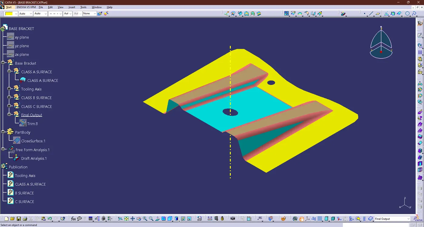
-
The technique used to create the model consists of first creating a Class B surface at a distance equal to the thickness (here 2.5 mm) and then a vertical Class C surface. Then Trim three surfaces to get the desired part.
- STEPS FOR CREATING THE CLASS B & C SURFACES:
- First we need the tooling axis so need to create the tooling axis
- The model is observed from 3 planes and the xy plane is selected for detail generation. Thus, the hole was taken into account and a point was created.
- Let the point is taken as a reference and a dummy tool line is generated. This line is then used to create a plane to sample the intersection.
- Then create two slopes on either side of the intersection are used to create two additional lines, and at the end a bisecting line is created to become the main tool axis.
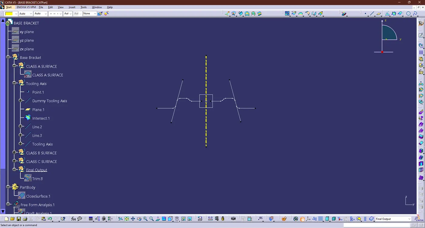
- DRAFT ANALYSIS:
- Now perform a draft analysis using the draft analysis tool included in the tools. Then, after opening the draft analysis toolbox, find the compass and align it with the axis of the tool, click the lock icon after alignment, and click add to the surface.
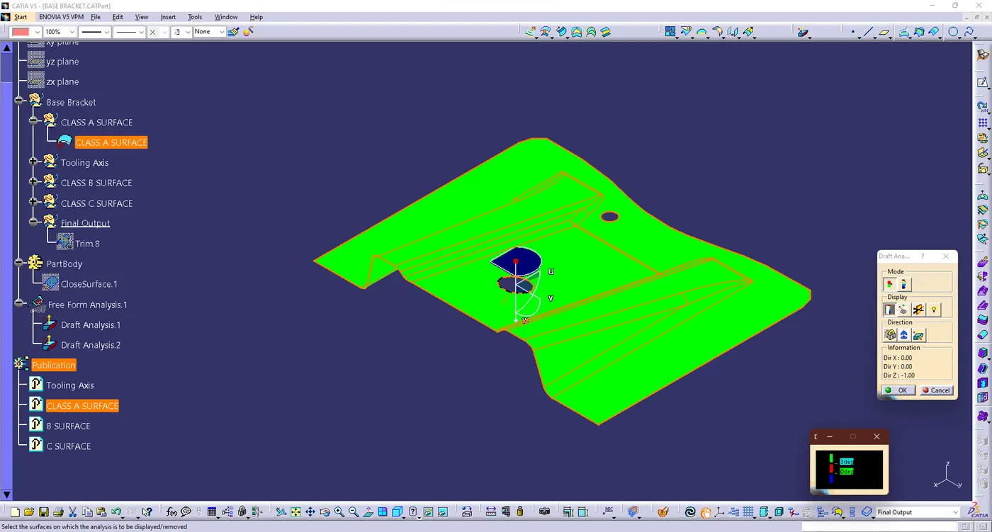
- Checking the surface it should lies on 0.5 to 3 deg and in our case it should lies on the 3 deg
- CLASS B SURFACE:
- A geometry set with name base bracket was created, then the entire Class A surface was extracted separately.
-
Then extracted surfaces of the RIB 1 and untrim to get a full surface and then extrapolated so that the clipping command can be executed successfully.
-
Then both sides were trim at the same time to have a offset the surface to 2.5mm.
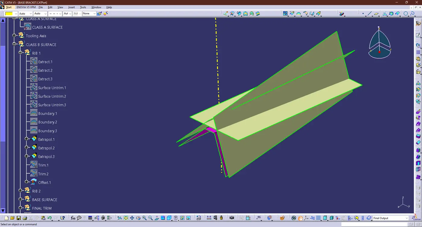
- Then same thing to do follow for the RIB 2
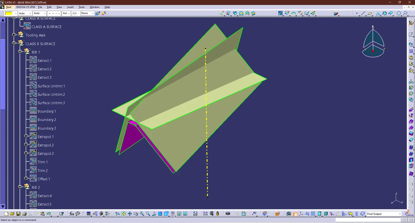
- Now create the connecting RIB portion same as before we do like extract the center region and untrim the surface and then extrapolated and do offset for 2.5mm.
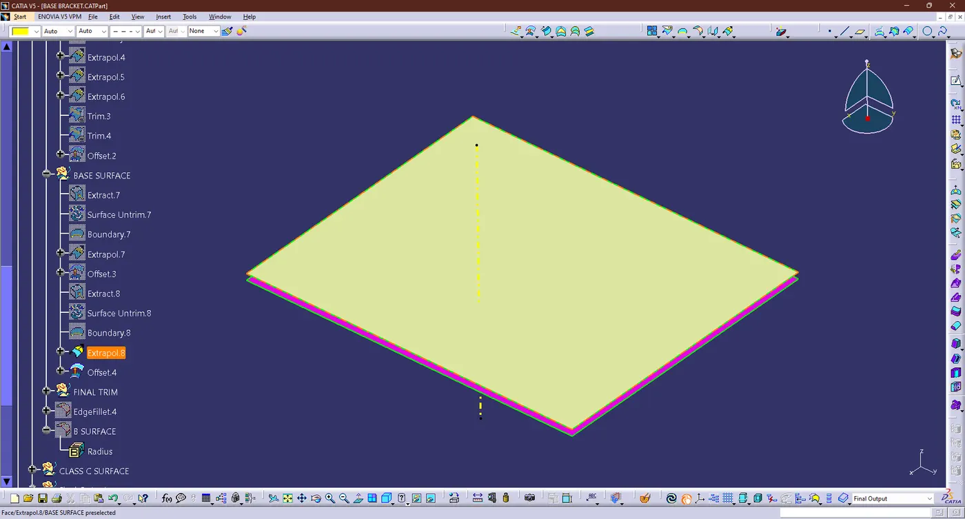
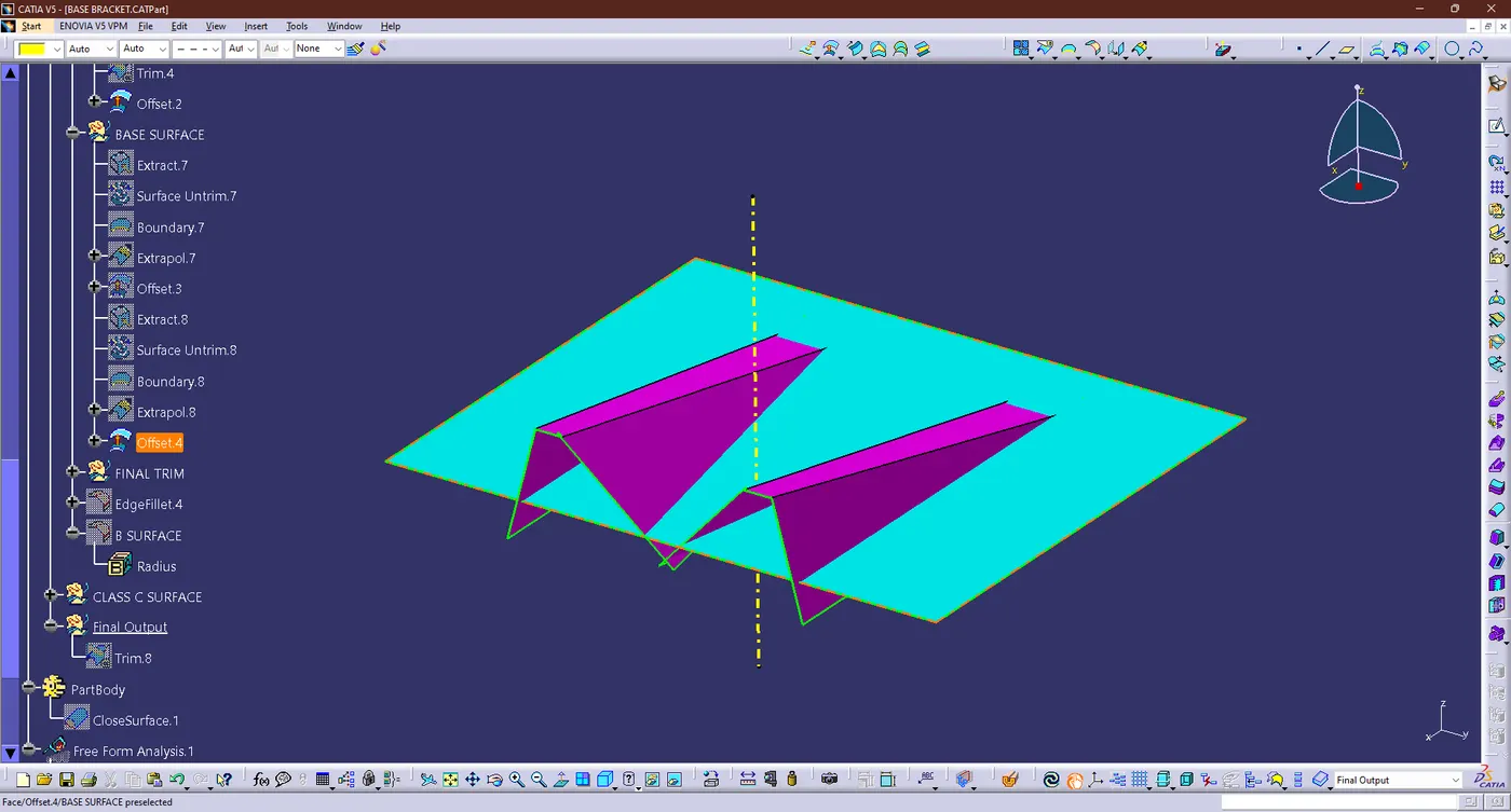
- Now trim all surface were we created like RIB1, RIB2, Connecting RIBs and it look like mention below,
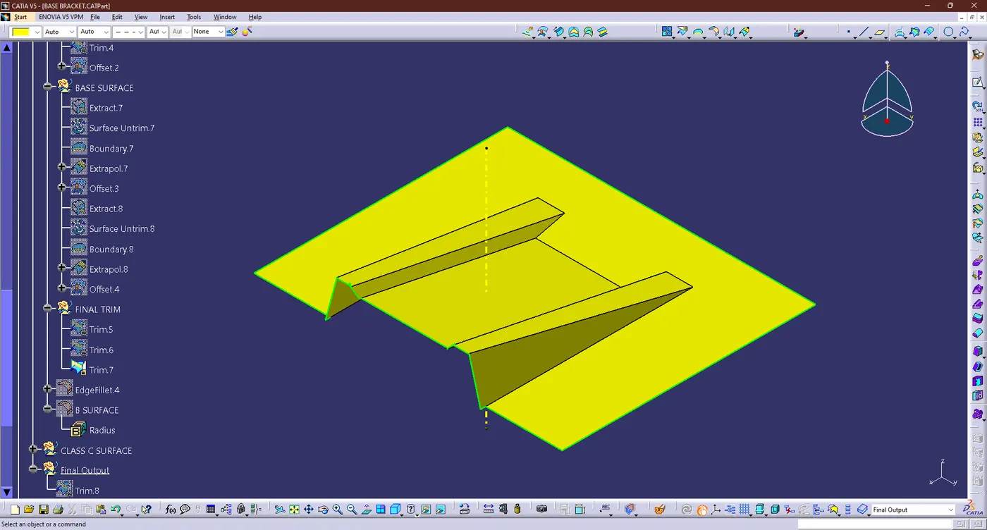
-
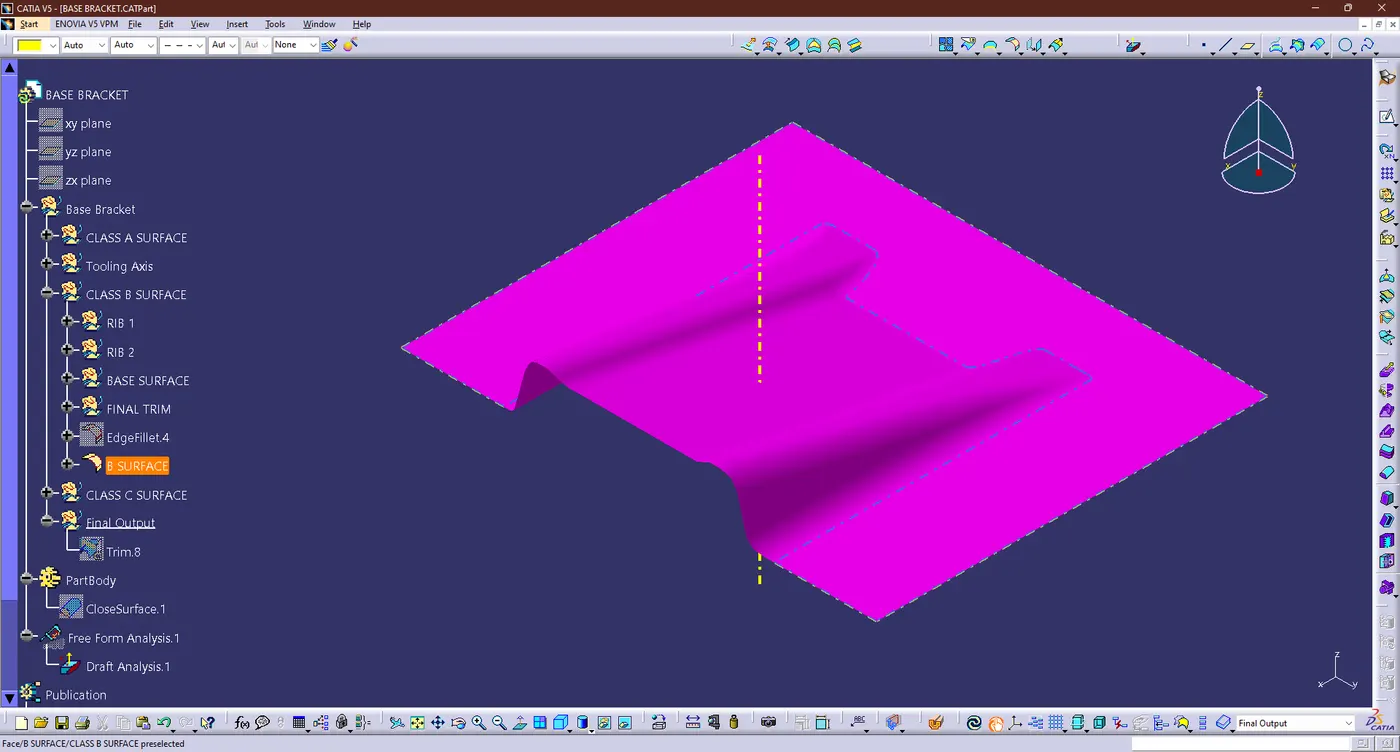
Surface B is made an exact copy of class A but at 2.5mm distance and without corners so the corners have radius+thickness value of part, i.e. 3+2.5 =5. 5 mm has been given.
- CLASS C SURFACES:
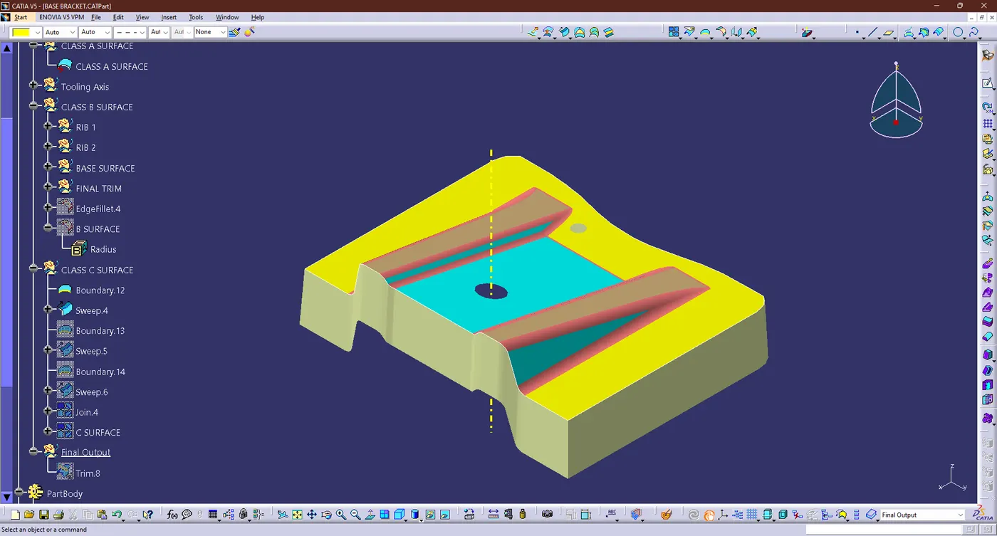
- The Boundary were create fo the class c surface from the class a surface
- Now using sweep command and given reference as main tooling axis, then given direction of the tooling were considered to create class C surface.
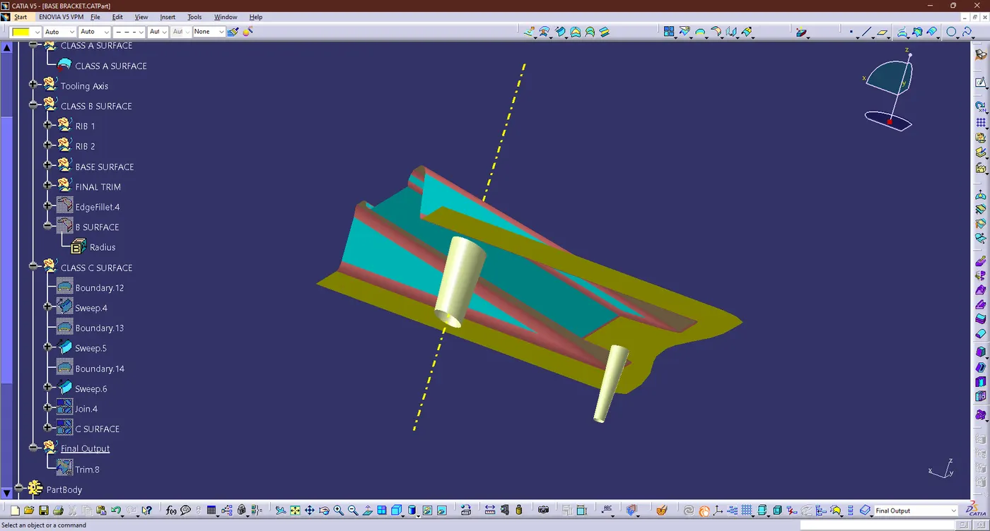
- Same thing to follow for the given holes
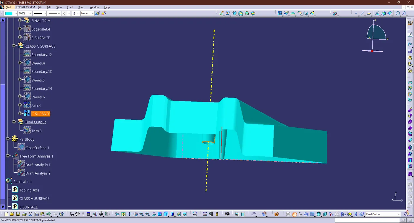
- Now join all the three sweep surface and it will shown like this mention below
- FINAL TRIM:
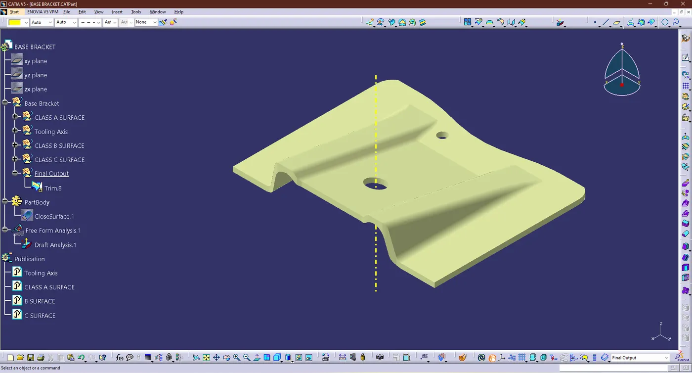
- Now trim all surface like CLASS A,B,C and we got final output were mention below
- DRAFT ANALYSIS:
- In plastic design, the draft analysis or angle that is considered in the OEMs is 3 degree.
- Same thing were do follow for the draft analysis on earlier and output mention below
- Then we got deg has 2.6 deg
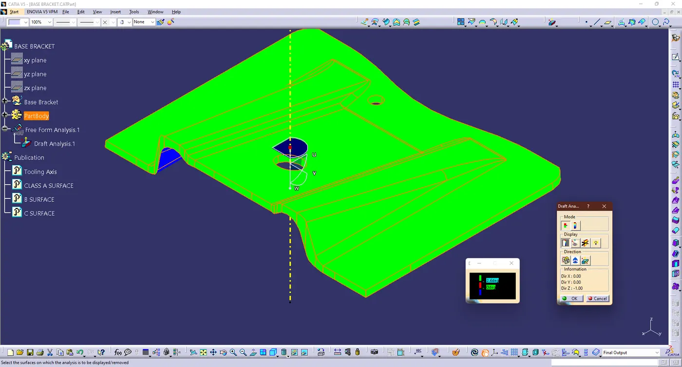
- Draft analysis on the solid part resulted in green, blue regions.
- The green area shows the part that can be machined or manufactured by the casting machine and the angle of inclination is 3 degrees.
- The blue area indicates that the part may be OK for some OEMs but still needs improvement for other manufacturers because the draft angle is greater than 3 degrees.
- A red color not appearing in this case indicates that the tilt angle is less than 3 degrees and cannot be manufactured or if manufacturing will be defective.
- SOLID BODY:
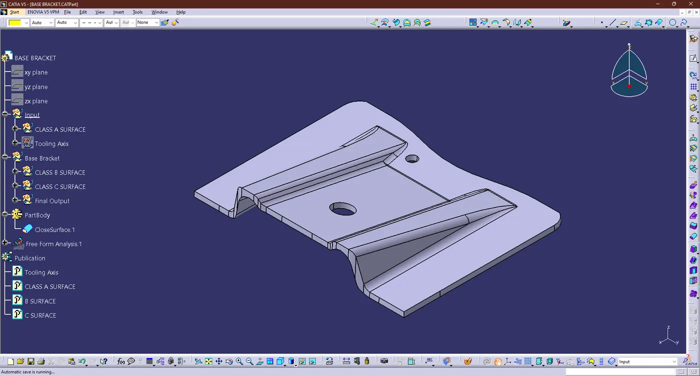
- The hollow is then created as a solid by selecting the Body option and then selecting the Close body surface and hence we got the final output were mention below
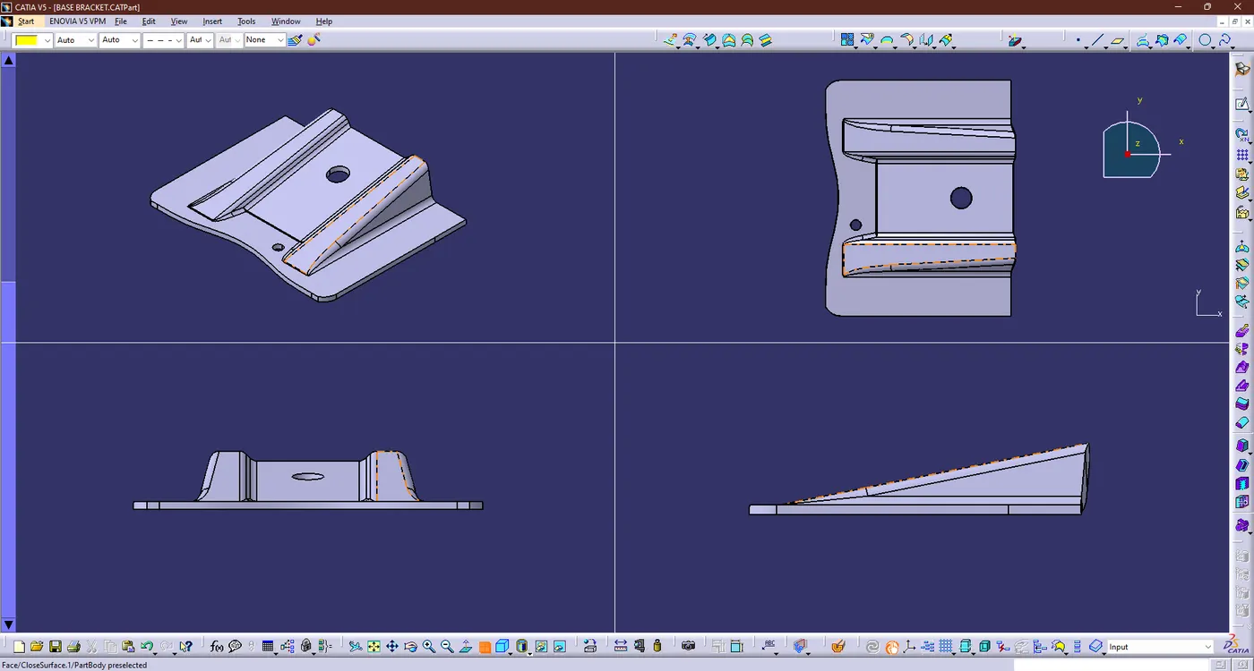
- DIFFERENT ORIENTATION WERE MENTION BELOW:
- TREE STRUCTURE:
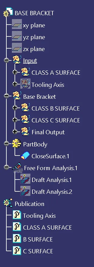
- FILES:
- The output file were mention on browe option in the name of the "week 9 challenge 1 (Base Bracket).zip" and also output image were upladed in the same folder.