Week 9 - Challenge 1 - Base Bracket Design
REPORT ON BASE BRACKET DESIGN
The Base Bracket design challenge incorporated the concept of using Class-A surfaces to create unique complex parts. Shapes/Sketches (Class-A Surfaces) for these parts are created using Autodesk Alias Software, which is then provided to the Automotive Product Designer to convert them to solid parts (Parts are created from a closed surface).
In this challenge, a Class-A Surface for the Base Bracket was provided to be converted into a solid part.
While working on the surface design of a plastic part, the manufacturing process should also be considered including concepts like the Tooling Axis, Draft Angle, uniform thickness of the component, etc. Therefore, before starting work on creating the solid part we must first do a Draft Analysis.
- What is Draft Angle?
It is the angle provided to product features like walls, ribs, bosses, etc which lie parallel to the direction of release from the mould.
- Why do we provide Draft Angle?
When the molten material solidifies, it shrinks and has the tendency to cling to the core. Therefore, if the walls of the solidified part and the mould components are at 90 degrees, it would result in the part and the mould components being in contact for the entire ejection process. The friction between them would result in a poor surface finish for the part and a shorter lifetime for the mould components.
As a result, a slight angle is provided to both the part and the mould components to help ease part ejection. Since, except for the first few millimetres the part will no longer be in contact with the mould components due to the draft angle.
Draft Analysis:-
The Draft Analysis tool in CATIA helps to identify the surfaces which deviate from the specified draft angle value along the defined tooling axis.
Tooling Axis is the direction in which the mould opens and it is also the direction in which the part is ejected. Therefore, the draft angle is provided with respect to the tooling axis.
Procedure for Draft Analysis:-
- First, we define the Tooling Axis.
An initial visual inspection of the Class-A surface can help in eliminating undesirable directions.
- The surface cannot be tooled from the Y-direction because the holes present on the surface would require side cores that would increase the manufacturing cost of the part.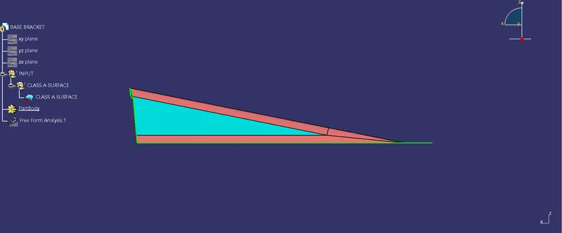
- X-direction also cannot be considered because of the same reason.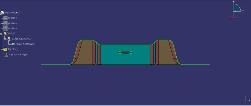
- In the Z-direction, holes lie perpendicular and can be easily tooled.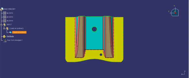
Therefore, we select the Z-direction and create a Dummy Tooling Axis to help us visualize the direction of the mould component's movement i.e. the direction in which the part will be ejected.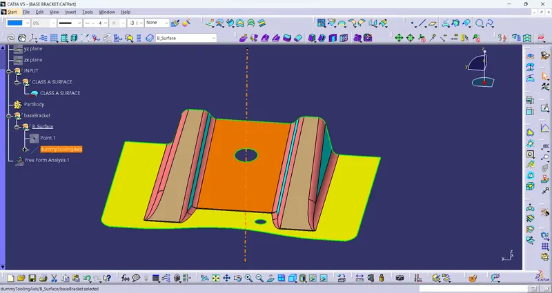
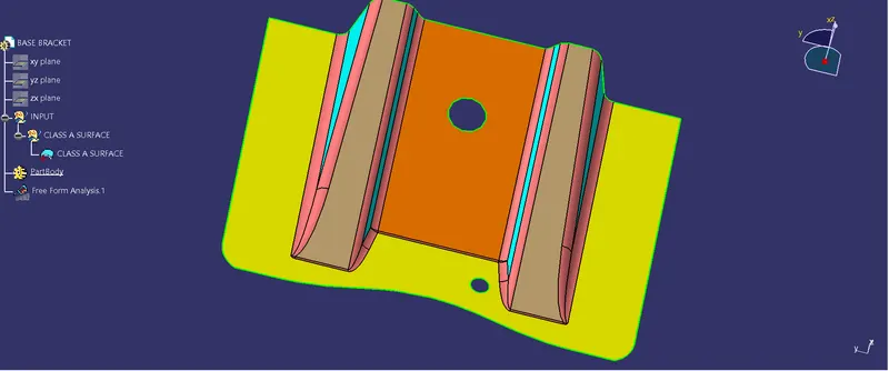
Surfaces which are parallel or at an angle lower than the Draft Angle with respect to the tooling axis should be highlighted as suspected problematic surfaces. We can then analyze these suspected surfaces to see if they clear the tooling axis.
- Surfaces that might cause problems while ejecting the part have been highlighted in Cyan, as shown in the below screenshot.
- Analysing the suspected problematic surfaces:-
The profile of the surface component lets us see more clearly the inclination of these surfaces. We can also use the measure tool to find the angle they make with respect to the tooling axis.
We create lines representing the surface inclination using the profile of the component.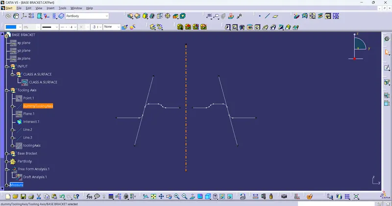
Then we create a line bisecting the two lines representing the surface inclination. This is done to get a tooling axis for that direction, that is at the same angle with the two surfaces, thus, making sure that our part gets ejected easily and without any damage.
The procedure is repeated in all directions that contain such suspected problematic surfaces, providing us with the tooling axes specific to the direction (in which the profile of the surface component is viewed).
Finally, we create a bisecting line using the direction-specific tooling axes to get the final Tooling Axis for the surface component.
In the case of the Base Bracket component, we find suspected problematic faces only in the X-direction. Therefore, the axis created to clear these faces can be deemed as the final Toolin Axis for our component (as shown below).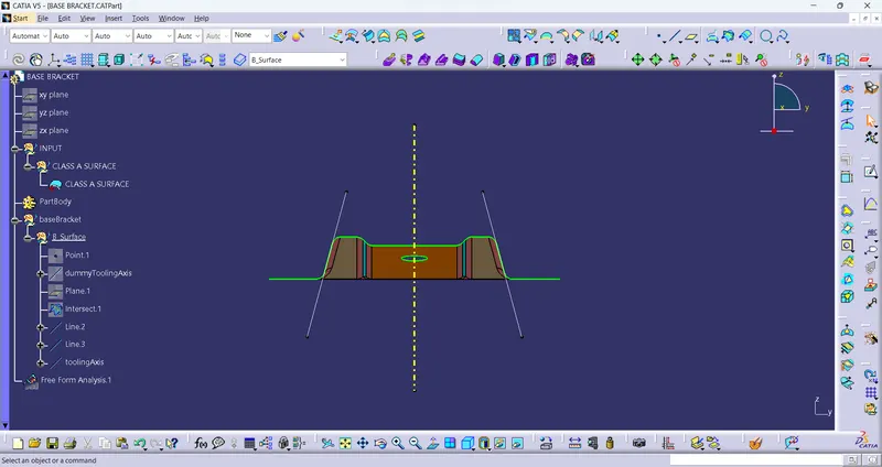
- Draft Analysis:-
Having defined the Tooling Axis we can now perform a Draft Analysis on the Class-A surface, to make sure that the surfaces have the desired draft angle and can be ejected easily without any damage.
- First, we change the View mode as required for draft analysis.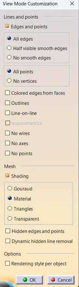
- Insert -> Analysis -> Feature Draft Analysis -> Select the Compass button -> Place the compass on the Tooling Axis -> Lock the compass -> Select the surface to perform the Analysis.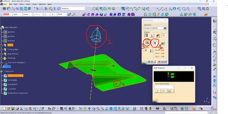
The Class-A Surface colour will change.
We have the colour code available in the second dialogue box, representing:
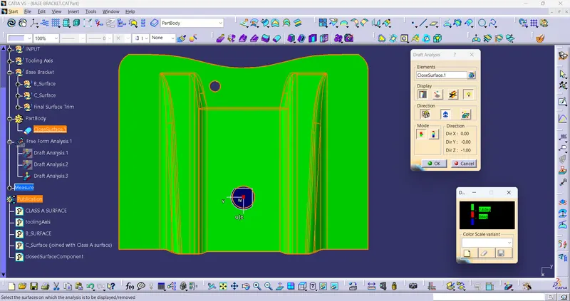
- "Green": Surfaces having Draft Angle above 3 degrees
- "Red": Surfaces with Draft Angle between 0 to 3 degrees.
- "Blue": Surfaces with a draft angle below zero.
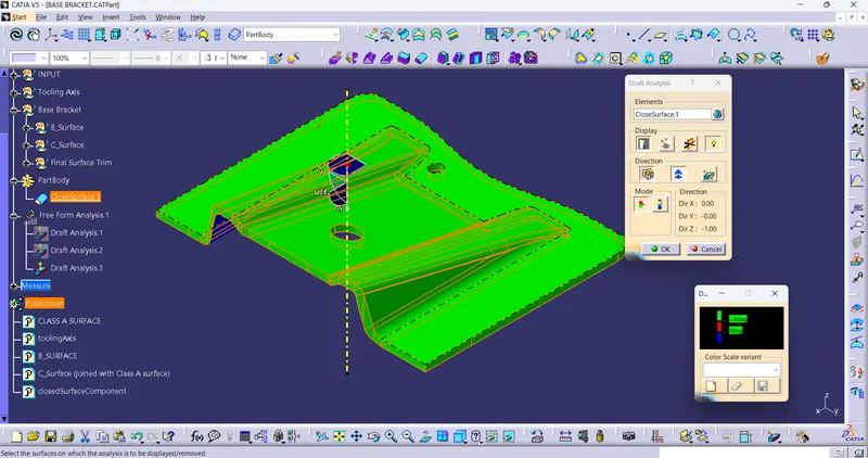
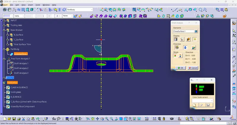
As can be seen from the screenshot above, the Base Bracket Class-A surface is completely Green, which shows that there are no problematic surfaces in the direction of the Tooling Axis and therefore the part can be easily ejected.
A Draft Analysis needs to be performed on the Final Surface Component as well:-
Following the same procedure as that for the Draft Analysis of the Class-A Surface, we get the following results.
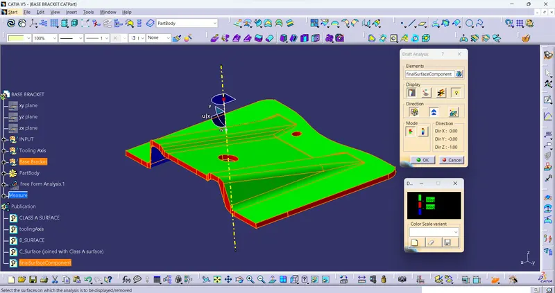
The top surface of our component is shown all in "Green", representing draft angles above 3 degrees for all the faces.
The "Red" coloured surfaces all belong to the C-Surface, this is because we gave the Draft Angle of exactly 3 degrees during the Sweep operation and the Green colour code is for surfaces with Draft Angle above 3 degrees.
If we edit the colour code, so that the Green colour represents surfaces above 2.9 degrees i.e. including surfaces having 3 degrees of draft angle, we get the following result.
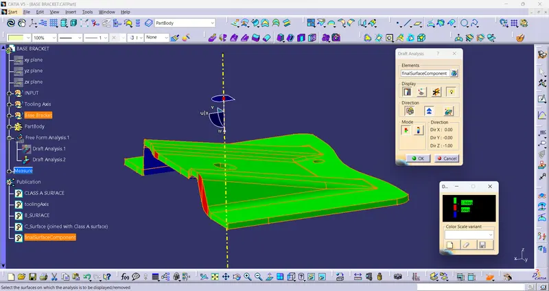
We can see that the majority of the C-surface is now in Green, which confirms our suspicion that the surfaces created using the Sweep command have a Draft Angle of exactly 3 degrees.
The remaining Red surfaces may be due to irregularities caused by Fillets, we can use the second option in the Display section to find out their draft angles.
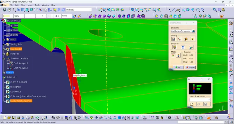
The draft Angle was found to be 2.664 degrees, so if we edit the colour code to have surfaces above 2.6 degrees represented in Green, we should cover the entire Final Surface Component.
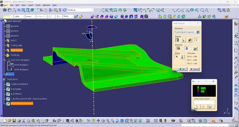
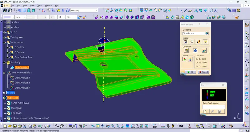
Finally, we perform a Draft Analysis on the solid plastic component as seen below. The results are the same as that for the Closed Surface Component.
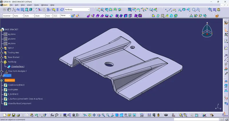
Isometric View
Front View
Top View