Project - Position control of mass spring damper system
Simulink Model using the transfer function of a mass-spring-damper system:
The equation of motion for a Spring Mass Damper system is as follows:-
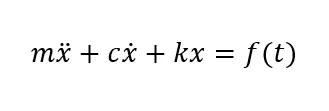
Using the Laplace transform on the equation of motion we get,
(ms^2 + cs + k)X(s) = F(s)
=> Transfer function (output/input) is:-
X(s)/F(s) = 1/(ms^2 + cs + k)
Next, we have to add a PID controller to adjust the force on mass so that its position follows a reference signal.
Values provided in the question:
m = 3.6; % Mass [Kg]
k = 400; % Spring Constant [N/m]
c = 100; % Damping [Ns/m]
Parameter values required to model the system response and design a PID controller are calculated below:
wn = sqrt(k/m); % Angular Natural Frequency (rad/sec)
zeta = c/(2*wn*m); % Damping Ratio
We can calculate the roots of the characteristic equation using the "roots" command, and plot them to check the system stability.
P = roots([1 2*zeta*wn wn^2]);
s = tf('s');
G1 = wn^2/(s^2 + 2*zeta*wn*s + wn^2)
pzmap(G1)
>> G1 =
111.1
---------------------
s^2 + 27.78 s + 111.1
Continuous-time transfer function.
111.1
---------------------
s^2 + 27.78 s + 111.1
Continuous-time transfer function.
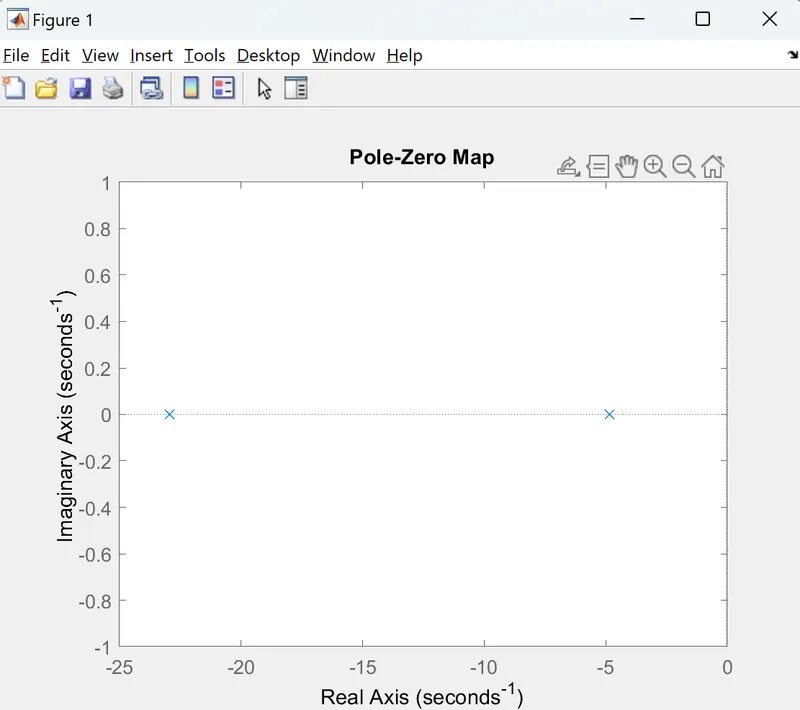
From the plot, we can see that the poles of the characteristic equation both lie in the left half plane of the s-domain. Therefore we can conclude that the system is stable.
Using the roots of the equation we can calculate the control gains, which can then be tuned in such a way that the system response follows the input reference and satisfy the control design objectives:
A = [0 1;-k/m -c/m]; % State Matrix
B = [0; 1/m]; % Input Matrix
C = [1 0]; % Output Matrix
D = 0; % Feedforward matrix
K = place(A,B,P);
Kp = K(1);
Kd = K(2);
Ki = 0;
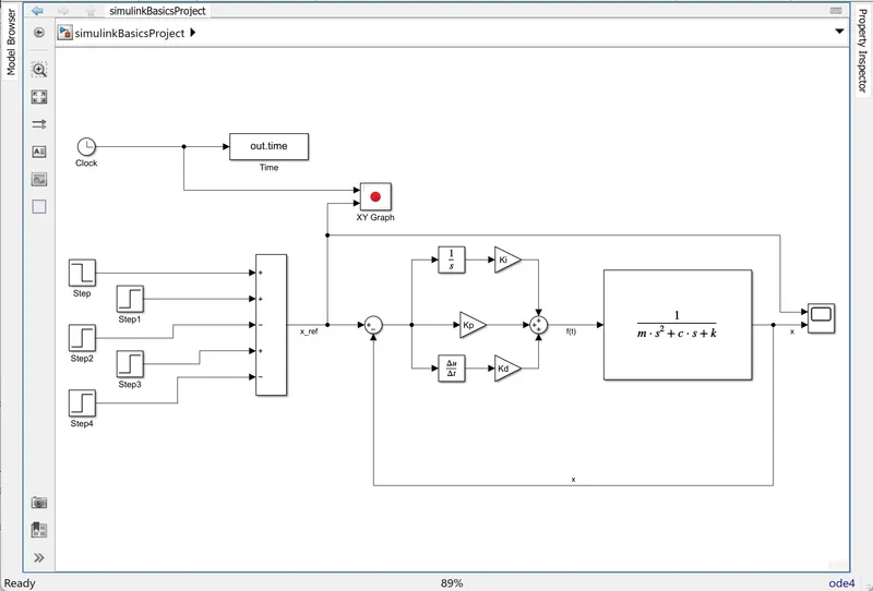
Equation of motion with PID control applied:
m*d2x/dt2 + c*dx/dt + k*x = f(t)
= Kp(x_ref - x) + Kd (dx_ref/dt - dx/dt) +Ki*∫(x_ref - x)dt
e(t) = xref - x
m*d2x/dt2 + c*dx/dt + k*x = Kp*e(t) + Kd*d(e(t))/dt + Ki*∫(e(t))
From the above-mentioned values and equation, a Simulink model can be created:
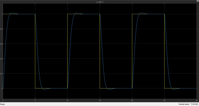
The response of the system with the control gains not tuned:
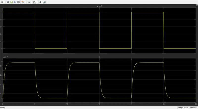
From the scope output, we can clearly see that the system follows the input reference but control gains are not able to provide the control effort to reach the reference value. Therefore we need to add Integral Gain (Ki) to remove the Steady State error and Proportional Gain (Kp) to reduce the Rise time.
For Control Gains: Ki = 1000, Kd = K(2), Kp = 100