Week 9 - Challenge 2 - Switch Bezel Design
REPORT ON SWITCH BEZEL DESIGN
- Tooling Axis Creation:
A shortcut to finding the Tooling Axis for a surface (as mentioned in the lecture videos) is to look for surface features like large planar areas or holes, the tooling axis often is the direction perpendicular to these features.
This is because even the Class-A Surface designers have the manufacturability of the part in mind while creating the Class-A surfaces. Therefore, they usually create surface features like holes and large plane areas in such a way that they can be easily manufactured.
Keeping that in mind, the Z-direction seems like a good direction to be the tooling axis.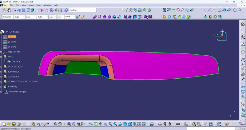
Since the two planar areas (in Pink and Green) can easily clear the Mould in the Z-direction, unlike in the X-direction where they were parallel and there are no Undercut features to worry about, unlike in the Y-direction.
There are three surfaces (in Blue) that are suspected problematic surfaces, therefore the Tooling Axis we define should be such that these surfaces can easily clear the mould during ejection.
Two of these are in the YZ plane and can be analysed by creating an intersect of the yz plane with the Class-A Surface, this will give us the profile of the surface in the YZ plane. We then create lines representing the suspected surfaces and use those lines to create a Bisecting Line which would be the Tooling Axis specific to X-direction.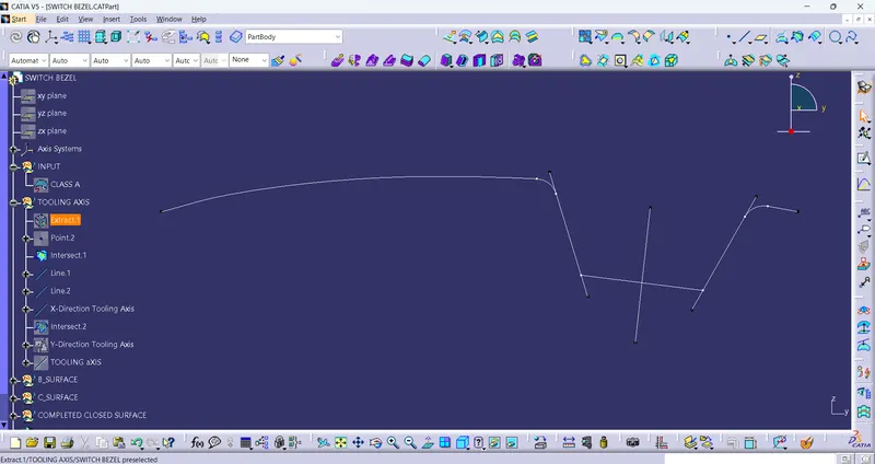
In the ZX plane we have only one surface, so we cannot create a bisecting line, instead, we directly create a tooling axis specific to the x-direction which is at an angle larger than the draft angle required.
The X-direction tooling axis is at an angle larger than the required draft angle because the final Tooling Axis will be created by bisecting the two direction-specific tooling axes and therefore might have a different angle wth the surface.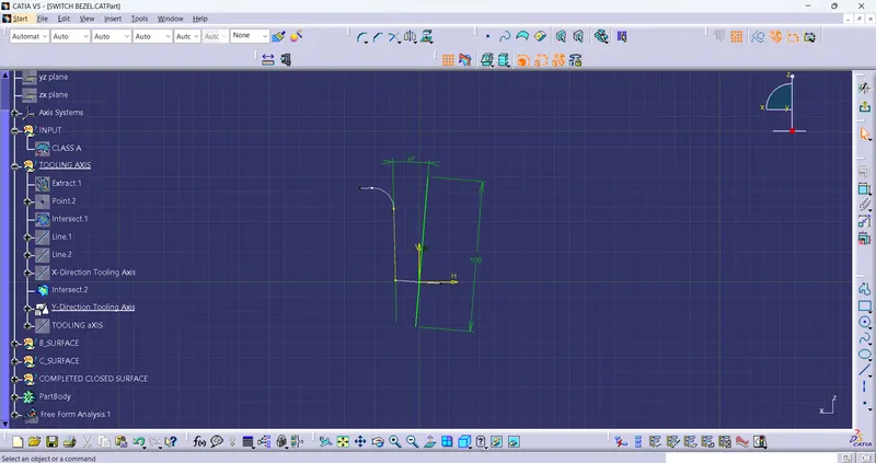
The Tooling Axis for the whole surface is created by bisecting the two direction-specific Tooling Axes.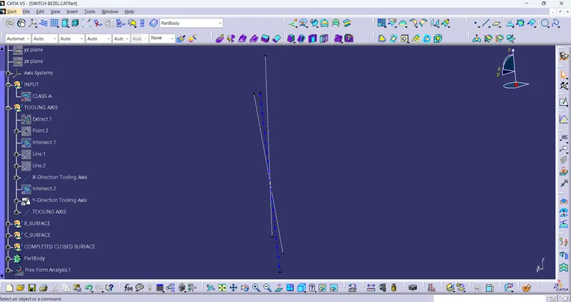
- Draft Analysis:
- Performing the Draft Analysis on the Class-A Surface shows that all the faces have required draft angles with respect to the tooling axis and therefore can be easily ejected from the mould.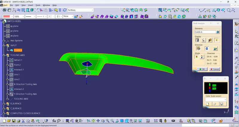
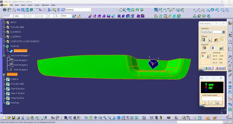
- We perform the Draft Analysis on the Closed plastic surface to make sure that the B-Surface and the C-Surface we created also have the required draft angle.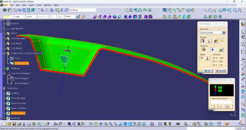
From the above screenshot, we can see that the C-surface does not have a draft angle of more than 3 degrees, this is because we gave the draft angle to be exactly 3 degrees in the Sweep command.
We edit the colour code for "Green" to include surfaces with 3 degrees draft angle.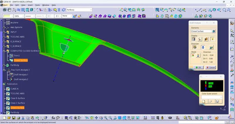
- Finally, we perform Draft Analysis on the solid Plastic Product.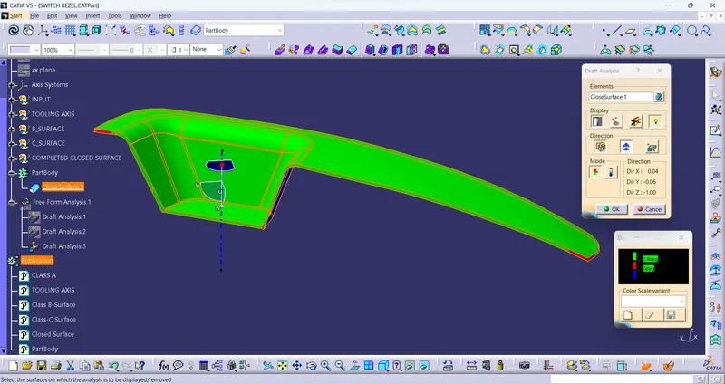
The result of the analysis is the same as that for the closed surface.
- Isometric View: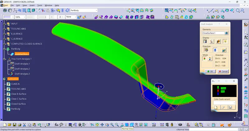
- Front View: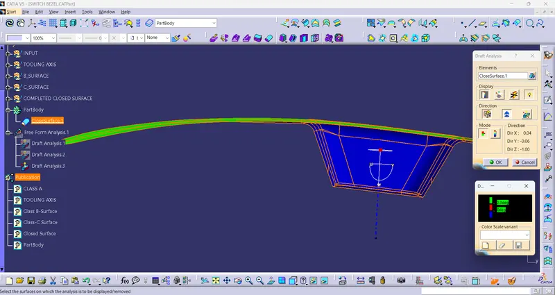
-Back View: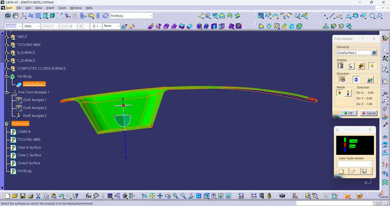
- Top View: