Week 9 - Challenge 1 - Base Bracket Design
AIM :-
- to Create the Base Bracket Plastic component through the given Class-A surface.
- To begin with, the tooling axis for the given Class-A Surface has be create meeting the require the draft angle and at the ending performed the Draft analysis on the model.
- The thickness has taken to the plastic part as 2.5 mm.
PROCEDURE FOLLOW FOR THE DRAFT ANALYSIS ON THE MODEL.
A] Tooling Axis procedure..
1] Varified the class a surface with the checking boundry & angle that is avg. 15.
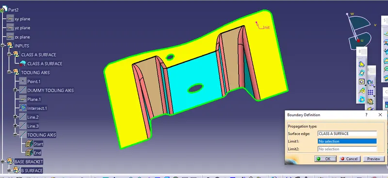
2] The point and Dummy Tooling axis has been created.
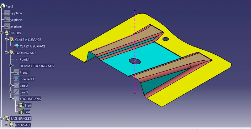
3] The plain & Intersections has created for the Tooling axis.
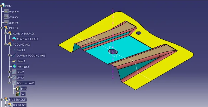
4] With the referance of the intersection boundry lines, that is parallel to the imaginary axis are created both sides,
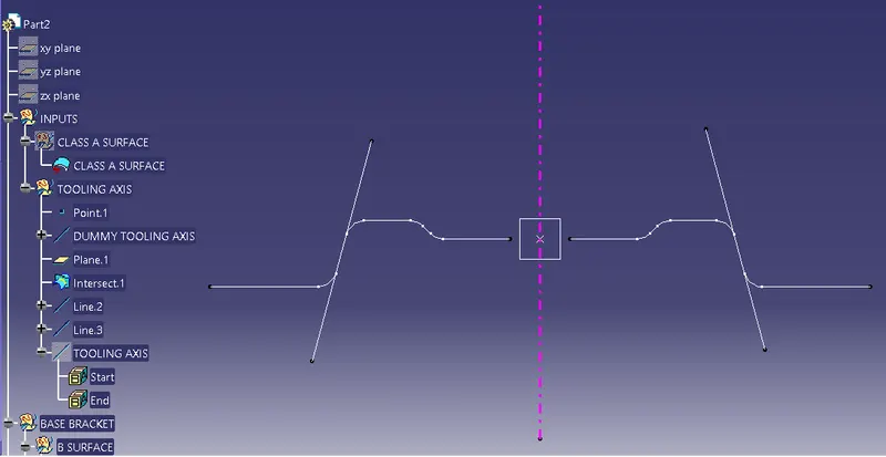
5] By the using line Bisecting with 2 lines with the point , the Tooling axis has got.
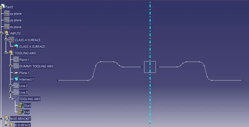
B] B_Surface (Ribs) procedure.
After getting the tooling axis, from the class A surface, take the 3 sides has exteacted of the Rib1. Namely as:
- Rib top
- big side parallel wall
- small side wall
Then hide it one by one. There got 3 surfaces and respectively untrimed all. This surfaces then extrapolated with exted 10 mm diamensions & Automatically hided the untrimed surfaces.
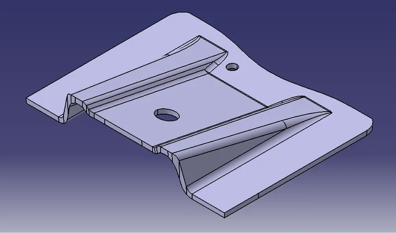
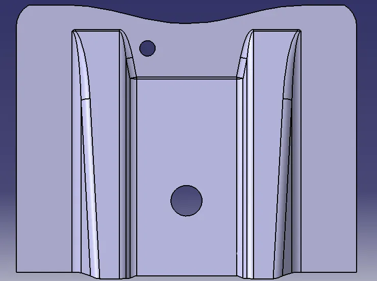
Again trimed that extrapolated surfaces and finally getting a one side Rib of B shape part. The snap is attached to the report as well.
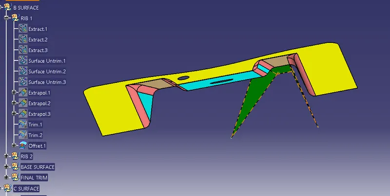
Just like Above procedure same left side one also meet, with an Offset has given as 2.5 mm diamension to it.
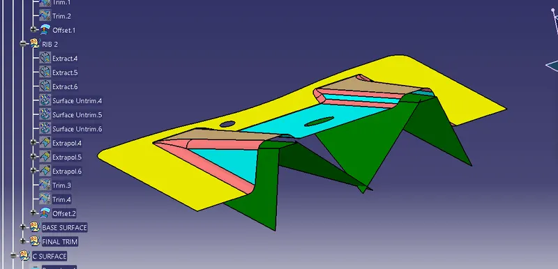
C] BASE SURFACES
Just like the rib created same the base and middle cap is extracted , then entrimed to it, offsested, and extrapolated .
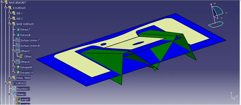
after the all there got a 2 Ribs with an base surfaces finally all together Trim to each with proper manner , Provided the 3 mm fillet radius to all corner & Finally got a B _SURFACE.
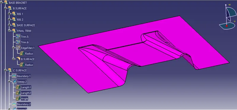
D] C_SURFACE PROCEDURE.
From the referance of class A surface. Taking a boundry, and make a sweep with an Angle 3 degree.
- Then sweep again to small hole with the tooling axis reverse direction extended 20 mm diamension.
- The big middle hole aslo swweped there.
- Then this 3 sweeps are join together &
- Trim each other.
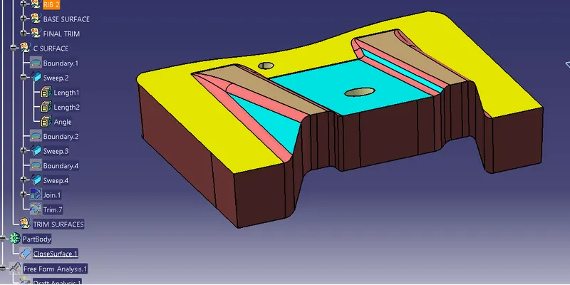
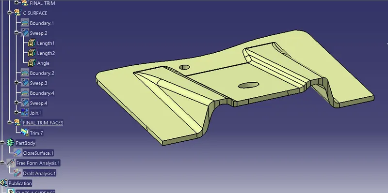
D] COLSED SURFACE
The final trim has maked the closed suface
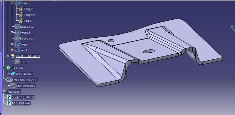
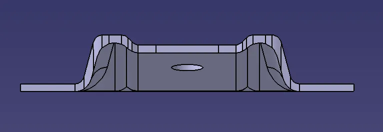
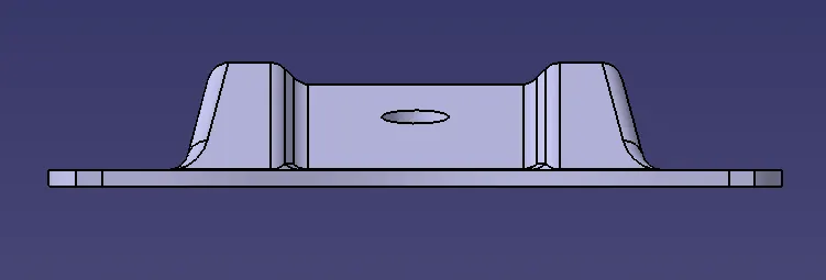
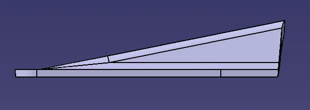
- Finally the all side views areattached to the report.
CONCLUSION :-
In this way the Draft Angle 3 mm diamension has done to the Base Bracket & the requied parameters with snaps has attached to the report with Cad_Part as well.