Week 9 - Challenge 1 - Base Bracket Design
Analyse the surface ,look for a suitable direction which can be used as a toolling axis.The Z axis can be used as the tooling axis as it does not need the additional use of side cores.So the center hole is selected.Create a point at the center of the hole and create a line along the z direction.
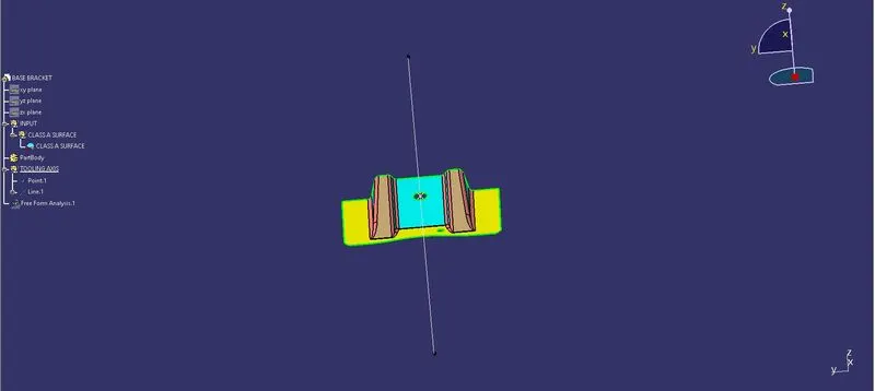
create a plane parallel to the yz plane at the center point.click the intersection option,select the elements and click ok.
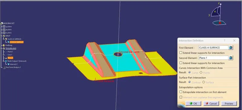
hide the surface .create two lines at the intersect portion where the angle is uncertain and extend them to suitable lenght.click create line,select as bisecting and select the two lines,select the center point ,select the direction and click ok.
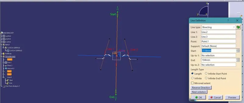
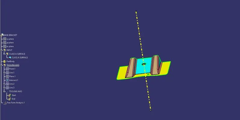
Name the bisecting line as tooling axis and give it a different width and color.
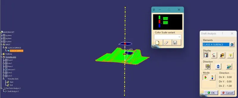
click draft analysis option ,drag and keep the compass on the tooling axis,and select the surface,it shows the part in suitable color,click ok.Then hide the draft analysis.
Insert a geometrical set,click on extract option and select the surfaces in the rib and click ok.
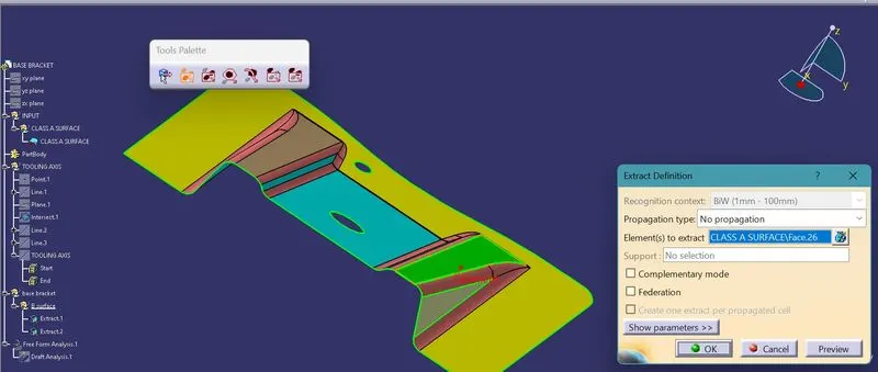
Then extracted surfaces are now seen.
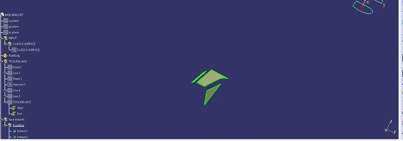
click on untrim option and select the surfaces.
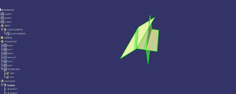
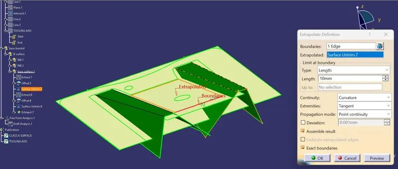
hide the extracts,click on expolate option and select the surfaces.,select point continuity for propagation and curvature for continuity.
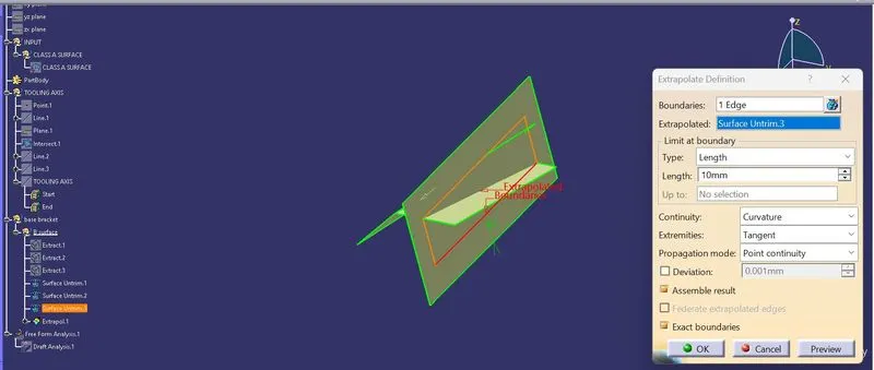
select the trim option,select the surfaces and remove the unnecessary parts.
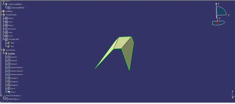
click offset option ,select it and give value as 2.5 mm.Give it a new color also.
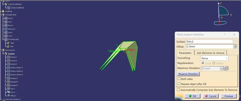
Do the similar process for the other rib also.
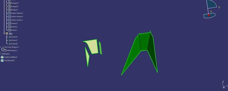
click extract and select the middle surface with the hole.Then untrim it,offset it by 2.5 mm and finally extrapolate it.
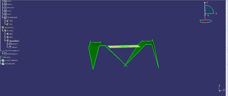
Extract the base plate surface,untrim it,offset by 2.5 mm,then extrapolate it .
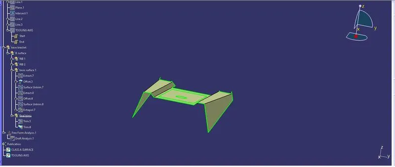
click the trim option and remove the unneceessary parts.
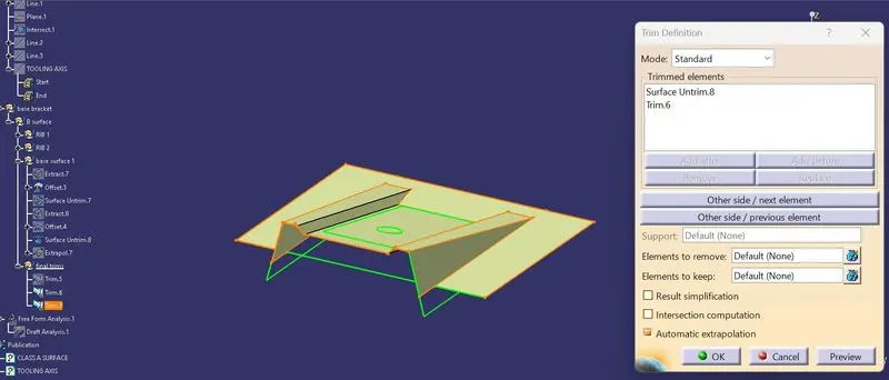
click on edge fillet option,give radius as 2.5+ 3 mm and select the edges.
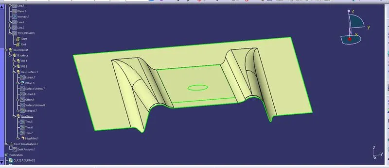
give it another color.This is named as the B surface.
Publish the A surface,B surface and tooling axis.
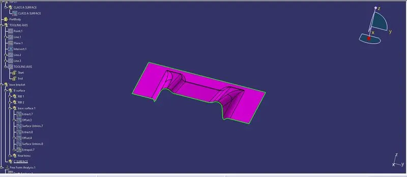
Show the A surface,click the boundary option,select the boundary of A surface and click ok.
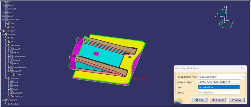
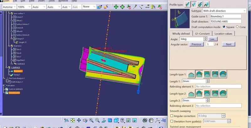
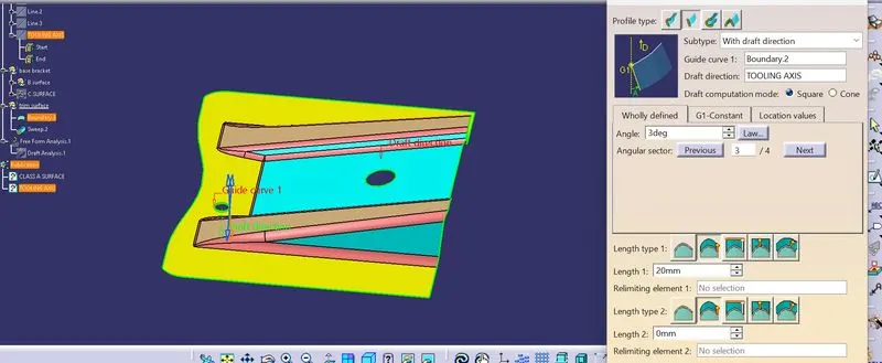
click on sweep option,select the second profile type,choose subtype as with draft direction,select the boundary as guide curve and give tooling axis as draft direction,length as 20 mm ,select the lower inward angle directiongive angle as 3 and click ok.
This is named as C surface and it is given a different color.
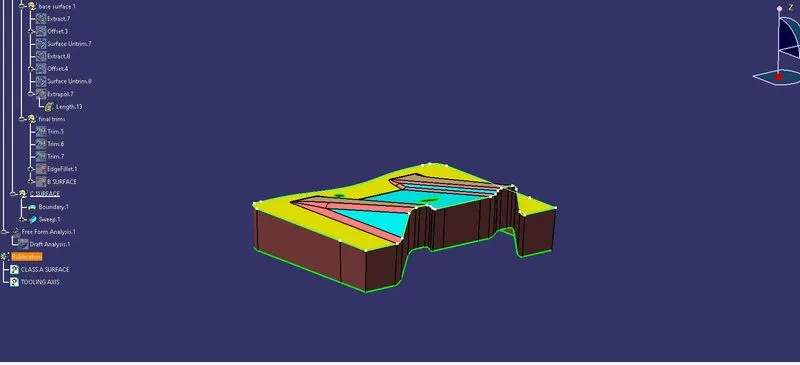
click boundary option,select the two holes of the A surface individually and select ok.
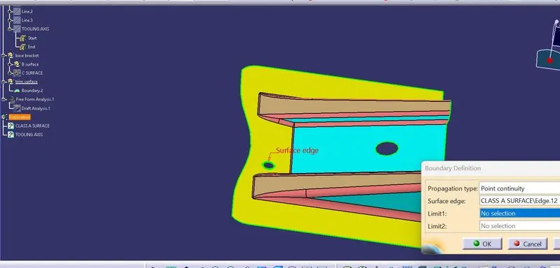
Click sweep option,select the two circles,given same details as the earlier sweep operation and click ok.
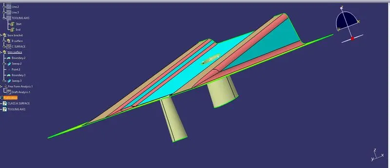
click join option and select the class A surface,C surface and click ok.
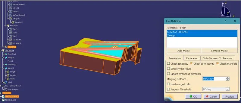
Do the join operation for both the sweeped holes also.
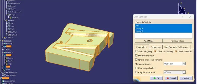
show all the surfaces.click on trim option,select the surfaces and trim the unnecessary parts and click ok.
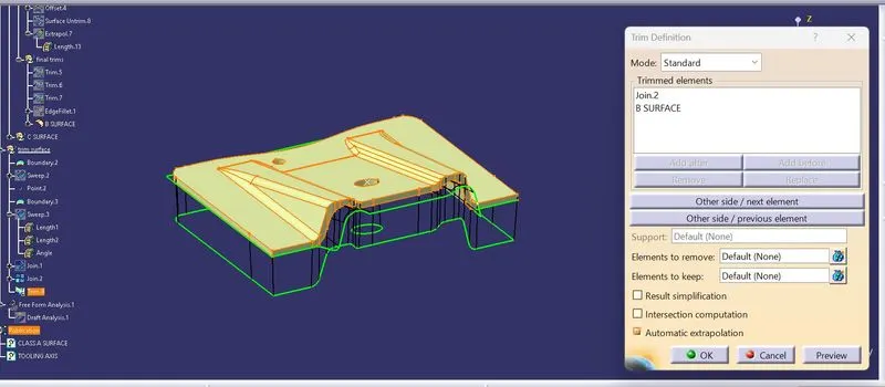
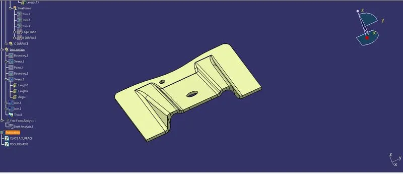
The complete part
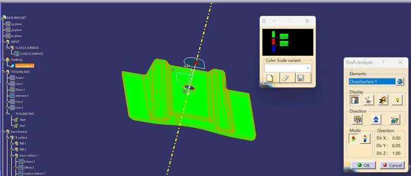
Go to part design,click close surface option and select the part,click ok.
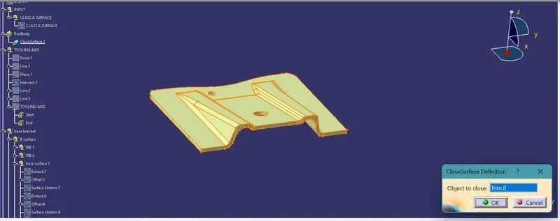
hide the trimmed part.
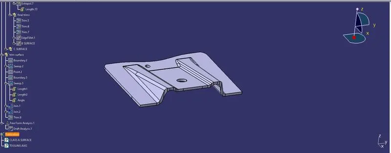
perform draft analysis on the part ,it shows that it is ok.
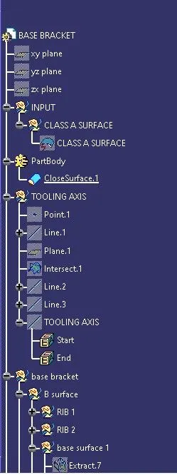
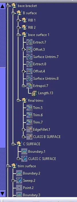
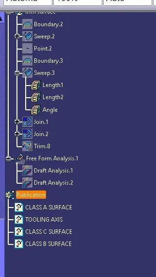
Tree structure