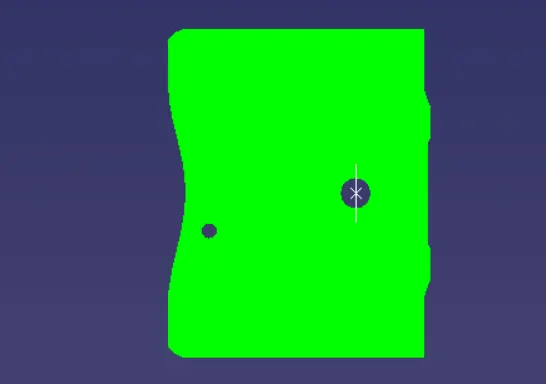
Week 9 - Challenge 1 - Base Bracket Design
AIM: Create the Base Bracket Plastic component through the given Class-A surface and perform the Draft analysis on the model.
Step 1: Examine the surface for connectivity.
- Begin by assessing the surfaces to ensure they are properly connected and form a continuous geometry. Identify any surfaces that are disjointed or not properly aligned.
- Next, employ the "join" command in CATIA to merge these separate surfaces into a single, unified entity. This process ensures that the surfaces are properly connected, allowing for accurate analysis and further modifications if necessary.
-
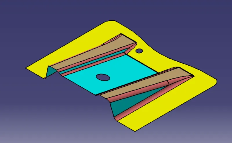
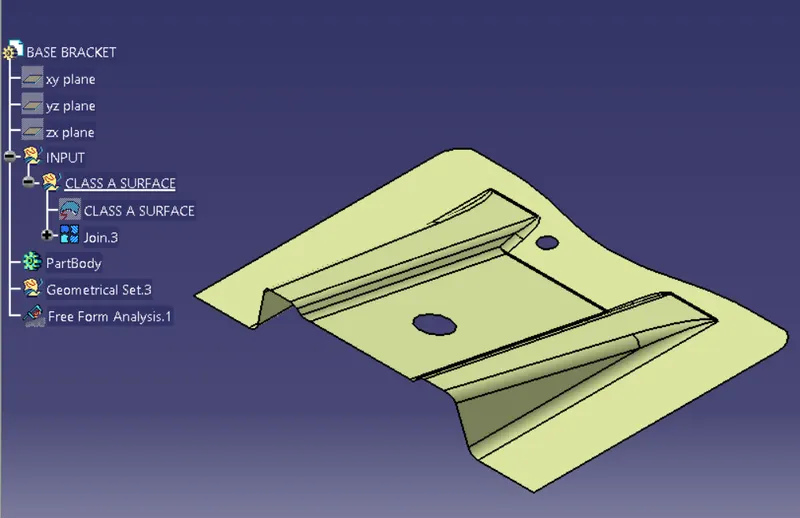
Step 2: Determine the tooling axis for the component, which refers to the direction in which the mold or cavity opens during the drafting process.
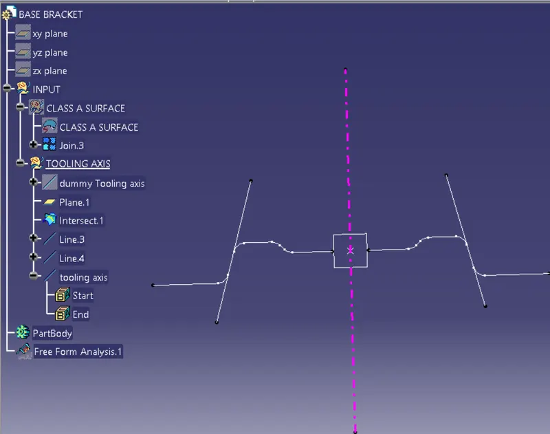
- Visually assess and identify the most optimal tooling axis among the available options. Consider all three axes: x, y, and z.
- After careful evaluation, it is observed that using the x-axis as the tooling axis would be feasible but costly, while the y-axis is not a viable option.
- However, the z-axis emerges as the most favorable tooling axis for the assignment.
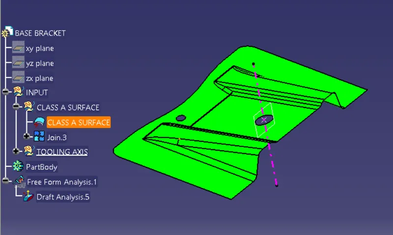
Step 3: Creating a Tooling Axis and Performing Draft Analysis:
- Create a line along the Z-axis to define the tooling axis.
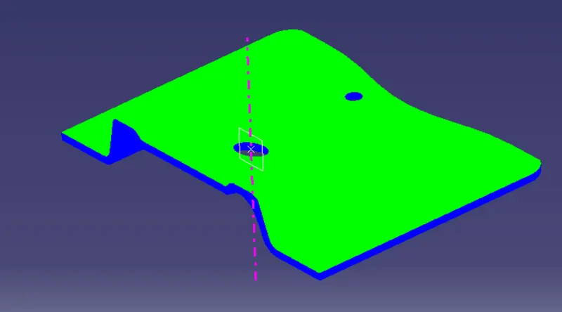
- Utilize the Featured Draft Analysis tool to analyze the component's draft angles.
- Access the draft analysis toolbox, align the compass with the tooling axis, and click the lock symbol.
- Click on the component's surface to apply the draft analysis and evaluate any issues or variations.
Step 4: Generating B Surface from Flat Faces
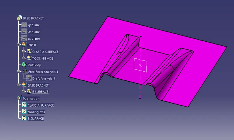
- Identify the flat faces on the surfaces from which the B surface needs to be created.
- Extract these flat faces from the existing surfaces.
- Untrim the extracted flat faces to restore their original extents.
- Extrapolate the untrimmed flat faces to extend them beyond their initial boundaries as required.
- Appropriately trim the extrapolated flat faces to achieve the desired shape and fit for the B surface.
Step 5:Creating C Surface.
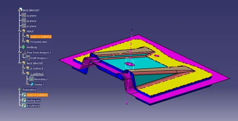
- Extract the boundary of the Class A surface.
- Utilize the "Sweep" command along the draft direction.
- Apply the extracted boundary as the path and select the draft direction.
Step 6: Trimming and Closing Surfaces to Create the Required Part
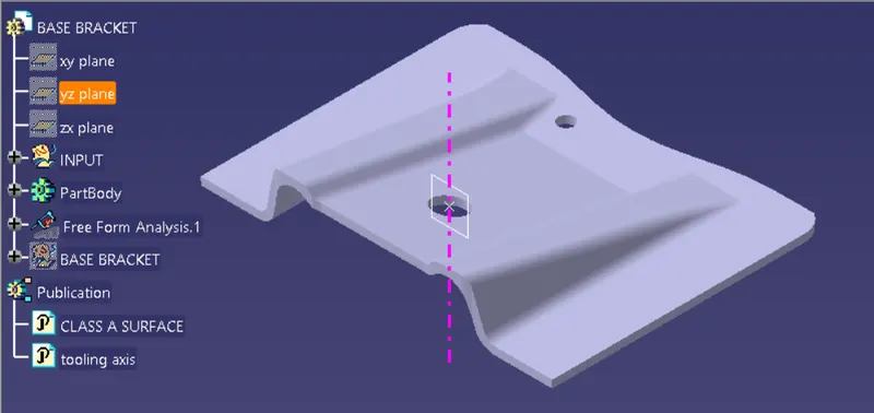
- Trim all the surfaces including Class A, B, and C to achieve the desired shape and fit.
- Ensure that the trimmed surfaces form a closed surface.
- Use the "Close Surface" command to convert the closed surface into a solid.
- ISOMETRIC VIEW
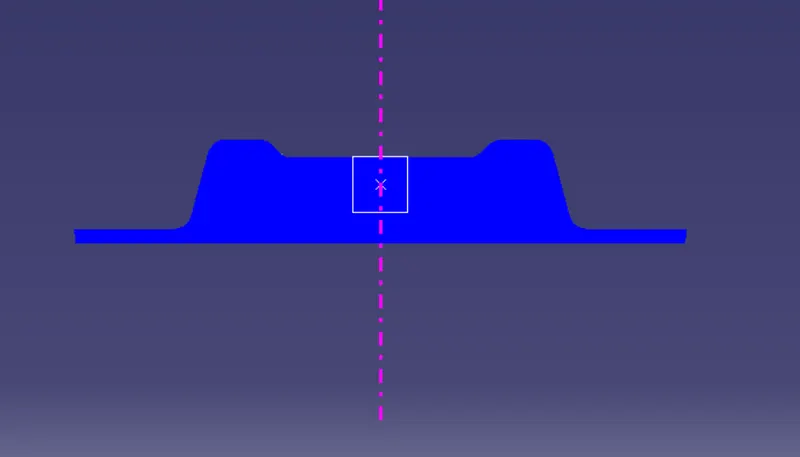
- FRONT VIEW
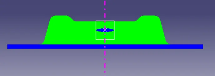
- REAR VIEW
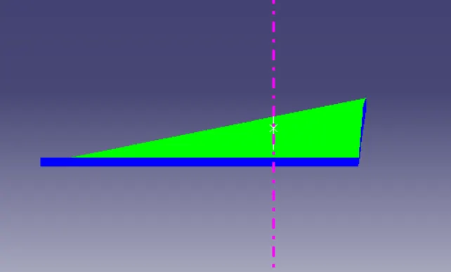
- SIDE VIEW
- TOP VIEW