Week 9 - Challenge 1 - Base Bracket Design
AIM: Create the Base Bracket Plastic component through the given Class-A surface and perform the Draft analysis on the model.
Thickness of Plastic Part - 2.5 mm
OBJECTIVES:
- Create a TOOLING AXIS.
- Create a Class B and Class C surface by using Class A surface.
- Create a solid body from the surface.
- Publications: Use the publication option and publish the below
- Tooling Axis
- Class A, B, and C surface
- Draft analysis of Class A surface and final Surface.
INTRODUCTION: In this project the Base Bracket Part is created from Class A surface. The steps used in the creation of Base Bracket Part contain creation of Class B Surface having the thickness of 2.5mm, also includes creation of Class C surface by using Parent surface which is Class A surface.
CLASS A SURFACE: Class A surface is the primary surface in the vehicle which is used as an reference surface in the creation of Class B surface.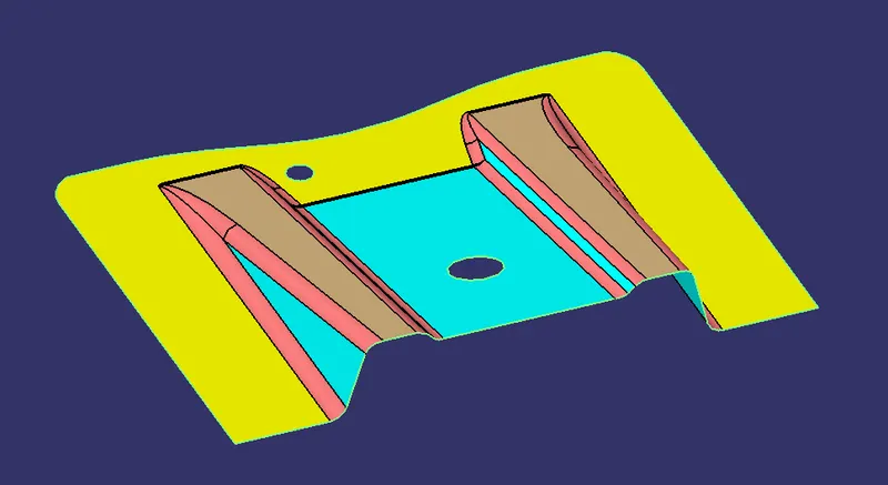
TOOLING AXIS : Tooling axis is the direction used in the manufacturing processes. The tooling axis is used to create component with positive draft angle which results in the manufacturing of component satsfying the requirements.
CREATION OF TOOLING AXIS : The tooling axis is created in this project by using the Bisecting Method.
- Creating the Point which is the centre of the hole or creating the Point intersecting the surface of the Class A surface.
- Creating the Plane passing through the Point perpendicular to the Class A suraface.
- Extracting the edge of the Class A surface on the plane by using Intersection command.
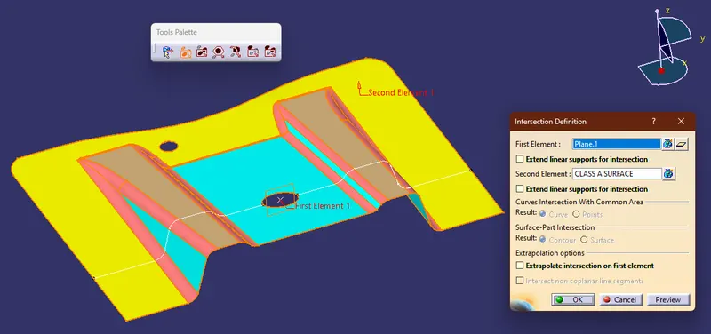
- Creating the lines passing through the inclined surfaces as shown in fig.
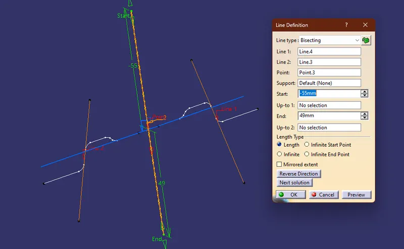
- This Bisecting line shows the tooling direction of the component. This is called as Tooling Axis which shows the direction of tool to be used in manufacturing of component.
CLASS B SURFACE: Class B surface is also called as an Engineering Surface. Class B surface is the surface created by using Class A surface at the thickness of the component.
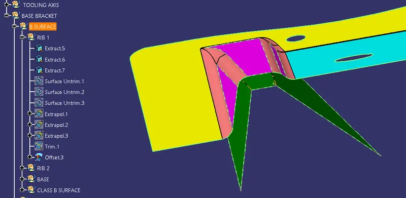
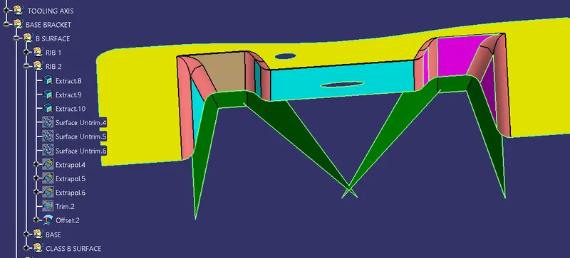
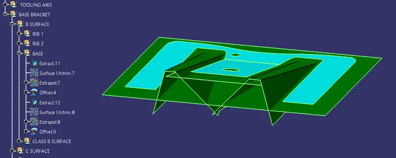
CREATION OF CLASS B SURFACE: Class B surface is created by extracting the surface from Class A surface and offsetting it by the thickness of the component. Class B surface contains Rib 1, Rib 2 and Base extracted from Class A surface. Steps used to create Class B surface are:
- Extract the flat surfaces like Ribs' top and inclined surfaces and Base surface.
- Untrimming all the surfaces seperately.
- Extrapolating edges of the surfaces by using Point Continuity till they intersect each other.
- Trimming the surfaces as like untrimmed Class A surface.
- Offsetting the trimmed surface upto the thickness of the component i.e. 2.5mm.
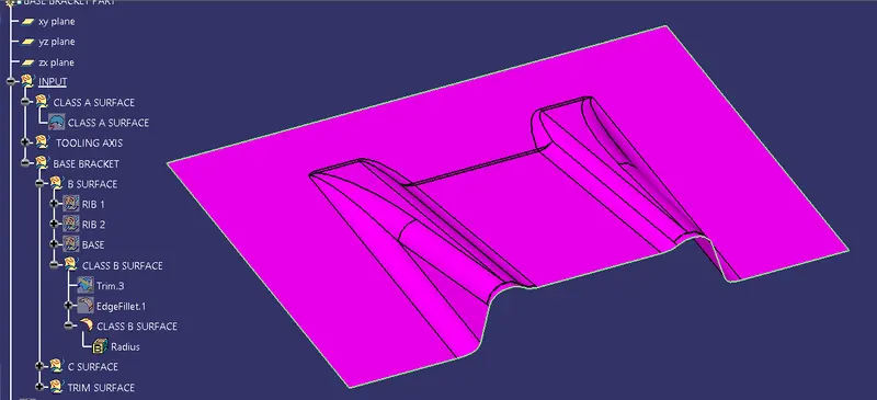
- Creating Edge Fillets as per the Class A surface. For example, for External fillet use Fillet Radius + Thickness of component and for internal fillets use Fillet Radius - Thickness of component.
- Class B surface is the trimmed and filleted surface.
RIB 1 :
RIB 2 :
BASE :
CLASS B SURFACE:
CLASS C SURFACE: Class C surface is the surface connecting Class A and Class B surfaces.
CREATION OF CLASS C SURFACE: Class C surface is created by using the Class A surface.
- Class C surface is created by extracting the edge and holes of the Class A surface.
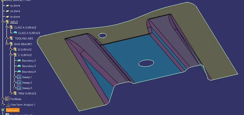
- Sweeping the extracted edge and holes along with the Tooling axis having Draft angle of 3 degrees towards the Class B surface.
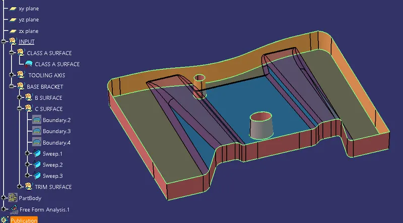
- These surfaces together called as the Class C surface.
FINAL TRIM:
Combining Class A and Class C surfaces together by using Join command.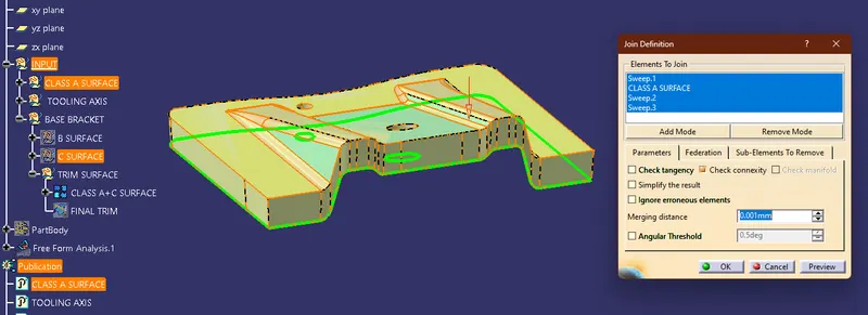
Trimming the Class A and Class C surfaces with Class B surface to get required surface of the component as shown in the fig.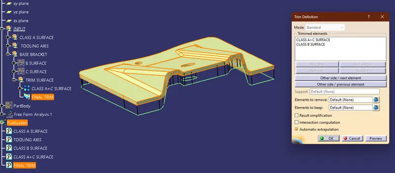
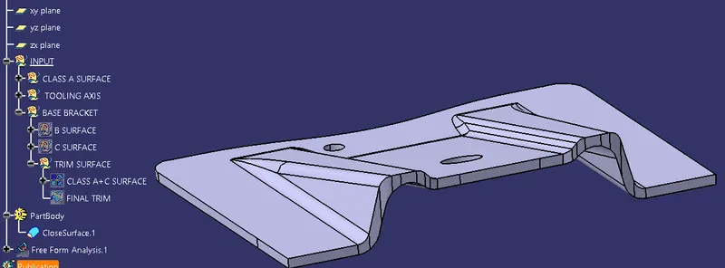
Changing the Workbench to Part workbench and using Closed Surface we can get Solid Part from the closed surface of the component.
DRAFT ANALYSIS:
Draft analysis on the Class A surface along the Tooling Axis is as shown in fig.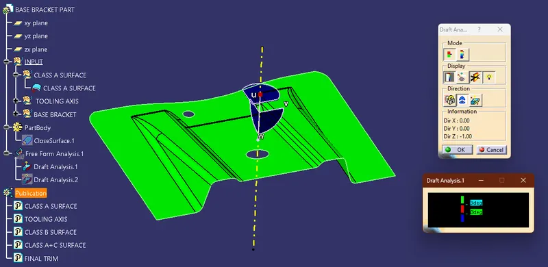
Draft analysis on the final component along the Tooling Axis is as shown in fig.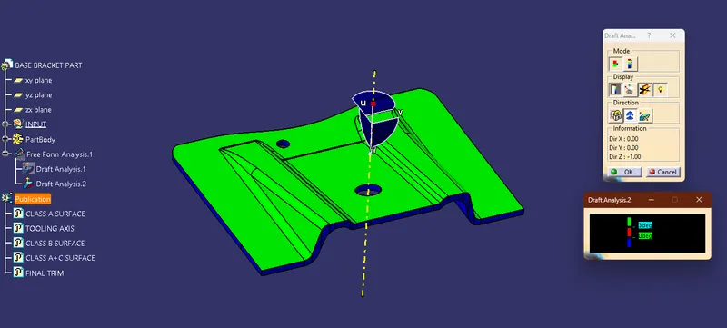
Front View :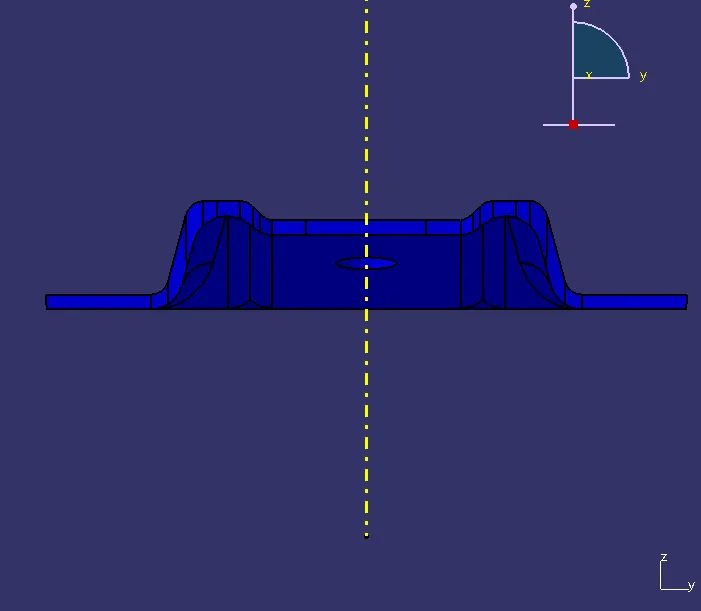
Side View :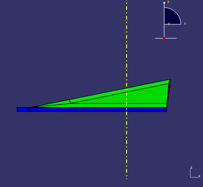
Top View :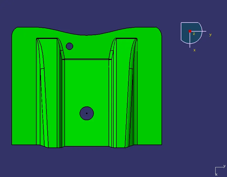
Isometric View :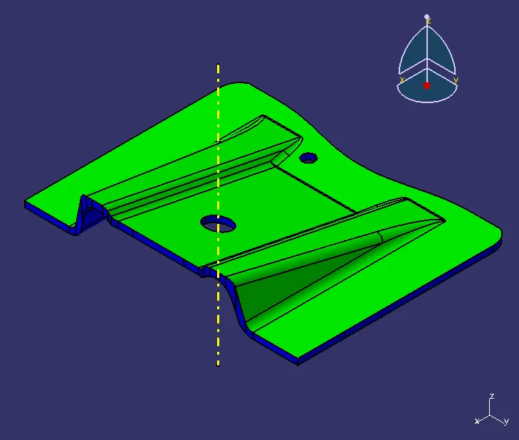
- Chinnamani PGOOD WORK