Week 9 - Challenge 1 - Base Bracket Design
WEEK 9 CHALLENGE 1- BASE BRACKET DESIGN
Create the Base Bracket Plastic component through the given Class-A surface. To begin with, the tooling axis for the given Class-A Surface should be created meeting the requirements of the draft angle and at the end perform the Draft analysis on the model.
Objective Of Challenge: To Create close body of base bracket, Tooling Axis Creation And do draft analysis of Class A surafce and Close body of base bracket.
Input: Class A surface Of Base Bracket
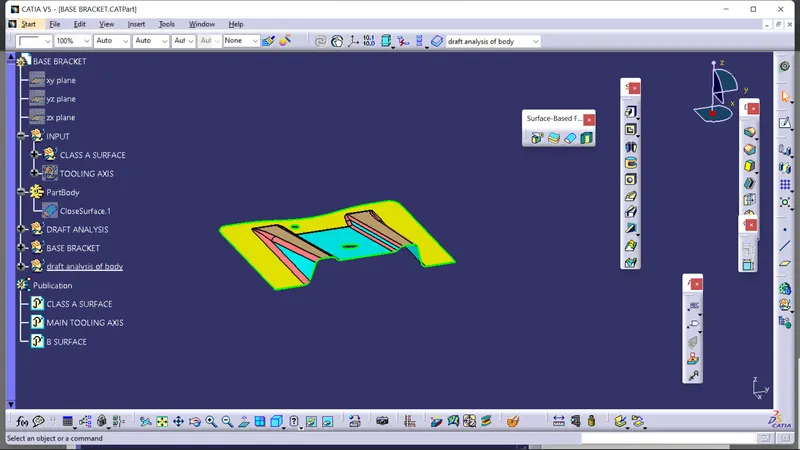
TOOLING AXIS CRAEATION:
- First we have to check the Class A surface should be complete one patch. there should no gap between any surface. check with the help of join or boundry command.
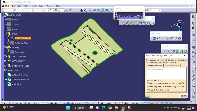
- choose the Tooling Axis such that The main Class A surface should be come clear in cavity along tooling direction. Tooling Direction is The Line in which Mould open and close . look by all diection and choose direction. Here it is looking two ribs and two hole looking clearly by XY plane.so we choosen z axis a Tooling Axis
- create dummy tooling axis
- take a intersection of Class A surface with Plane drawn.
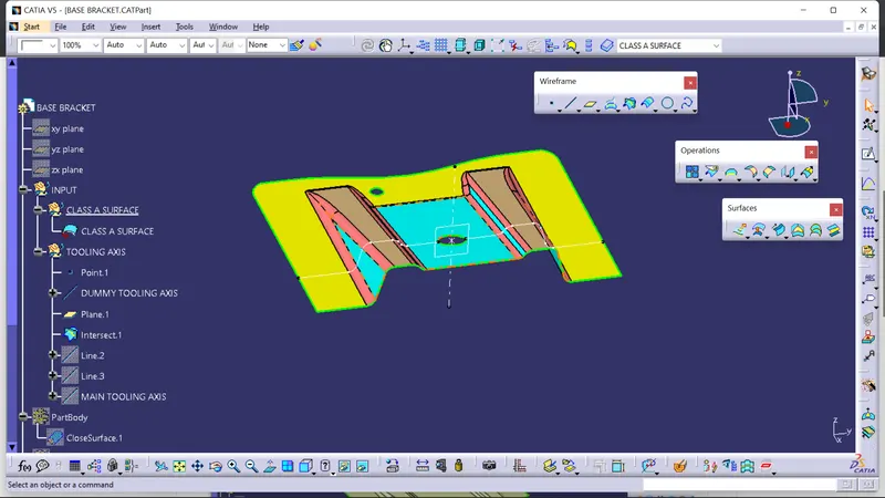
- create main tooling Axis by bysecting the lines which lies on Class A surface.
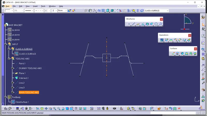
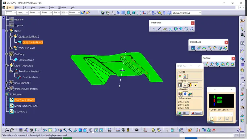
DRAFT ANALYSIS : - go to INSERT> ANALYSIS >FEATURE DRAFT ANALYSIS for draft analysis of Class A surafce . Drag the Axis system on Tooling Axis And select Class A surface.Define The range Of Dratf Angle Like 0-3,3-above.
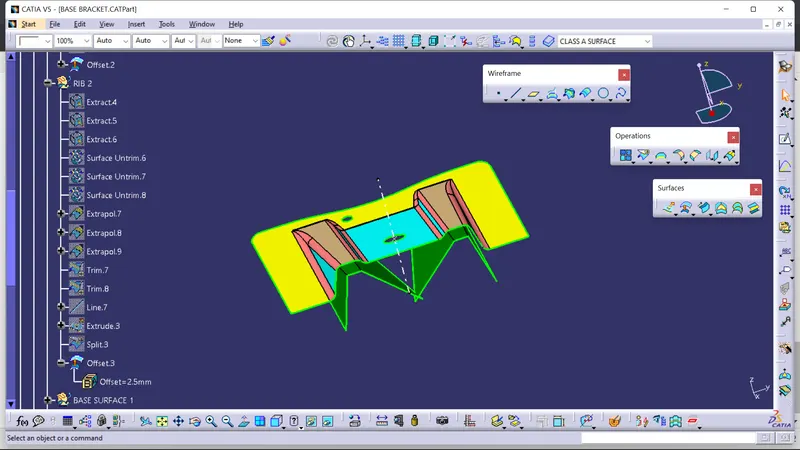
CLASS B SURFACE CRAEATION: - By using Extract , Surface Untrim, Extrapolate, Trim, Split , Offset Command Created the Offset Surfaces of ribs.
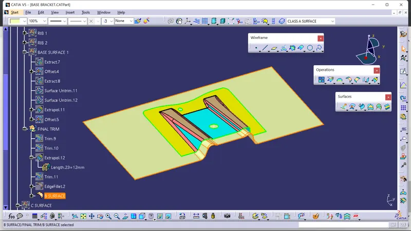
- Created offset to base by helping the above command Created The Class B Surface.
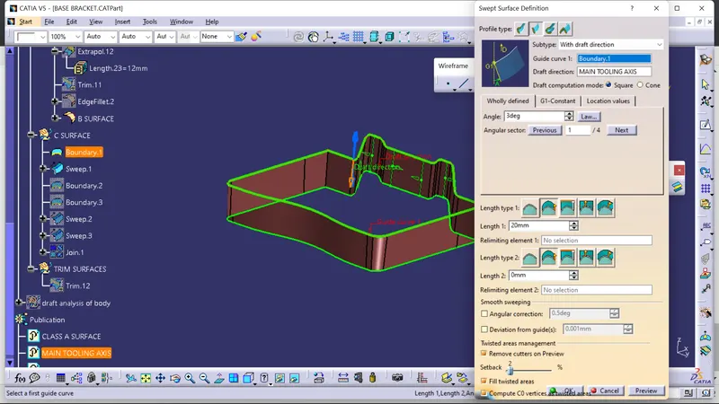
CLASS C SURFACE CREATION - create the Boundry By BOUNDARY Command ,to create class c surface. here three boundry we get.
- sweep the boundary and give angle of 3 degree length much more than thickness of part
- join all Class C and Class A suface
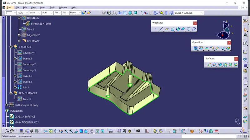
- trim the Class B surface from Joined Surface
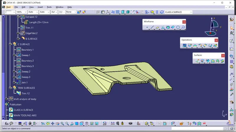
- create Body From closed Surfaces by CloseSurface Command.
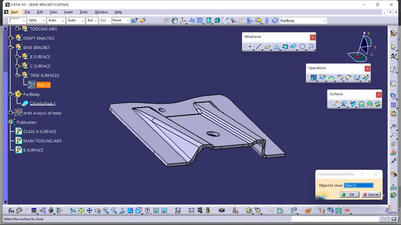
DRAFT ANALYSIS OF BODY: - Apply material to body by customised view parameter and the go to INSERT> ANALYSIS> DRAFT VIEW ANALYSIS .
drag the Axis system on Tooling Axis,select body and define draft angle parameter.