Week 9 - Challenge 3 - Bumper
BUMPER DESIGN CHALLENGE
AIM: To Create the Bumper Plastic component through the given Class-A surface. To begin with, the tooling axis for the given Class-A Surface should be created meeting the requirements of the draft angle and at the end perform the Draft analysis on the model.
INPUT: Class A surface
DESIGN PROCEDURE:
- TOOLING AXIS CREATION AND DRAFT ANALYSIS OF CLASS A SURFACE:
The first step is to check the continuity of the class A surface. This is to ensure that there is no gap between surfaces. If we find any then we should fix that first.we can ckeck by using boundry or join command command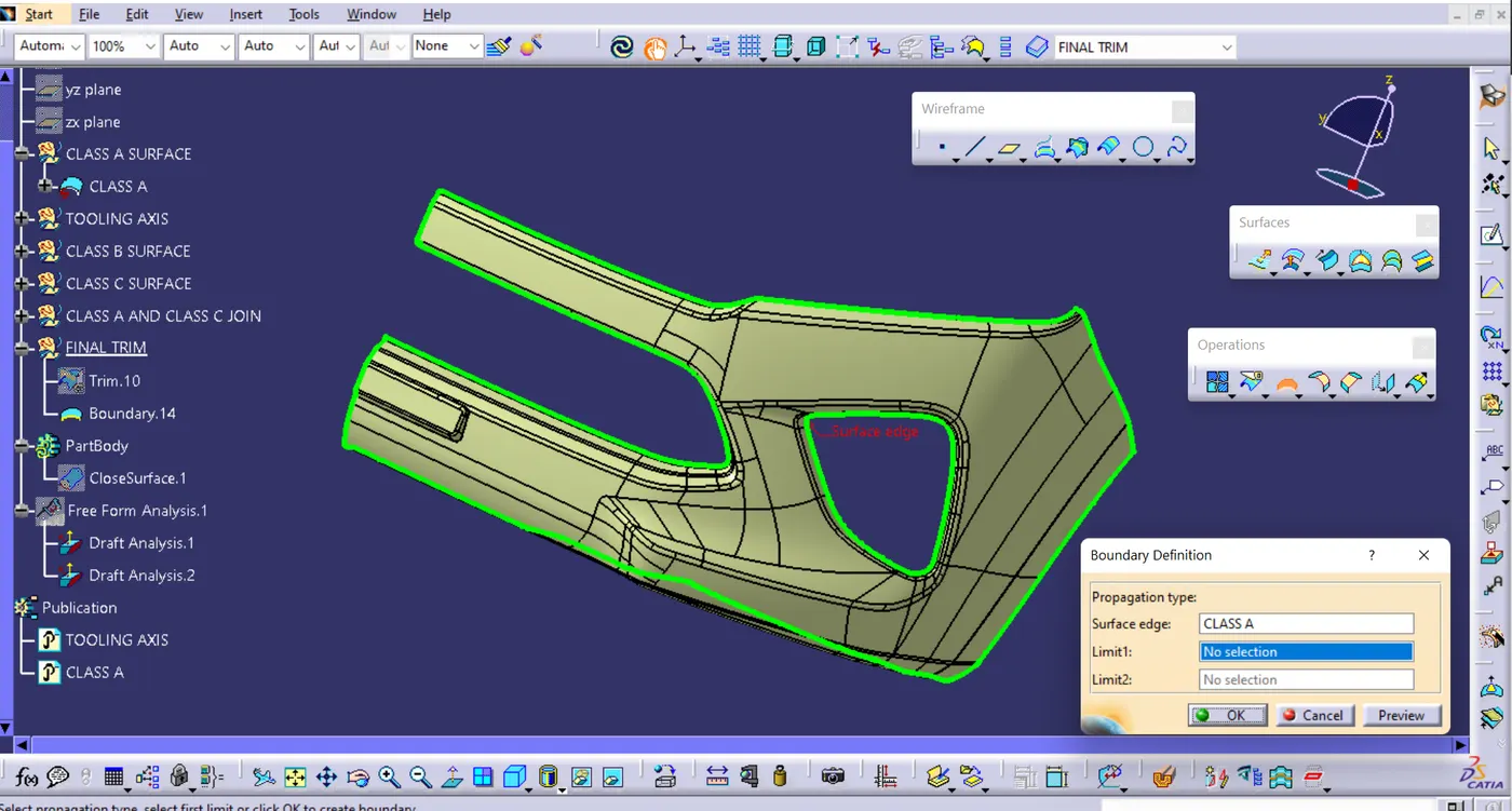
- select the Tooling Direction Such that all Class A surfaces should visible and So able to mould in that tooling direction.
- Here we can find out that the best tooling direction for the pumper class-A surface is along x-axis direction.
- take a point on Class A surface and Create Axis through the point Along X Direction.
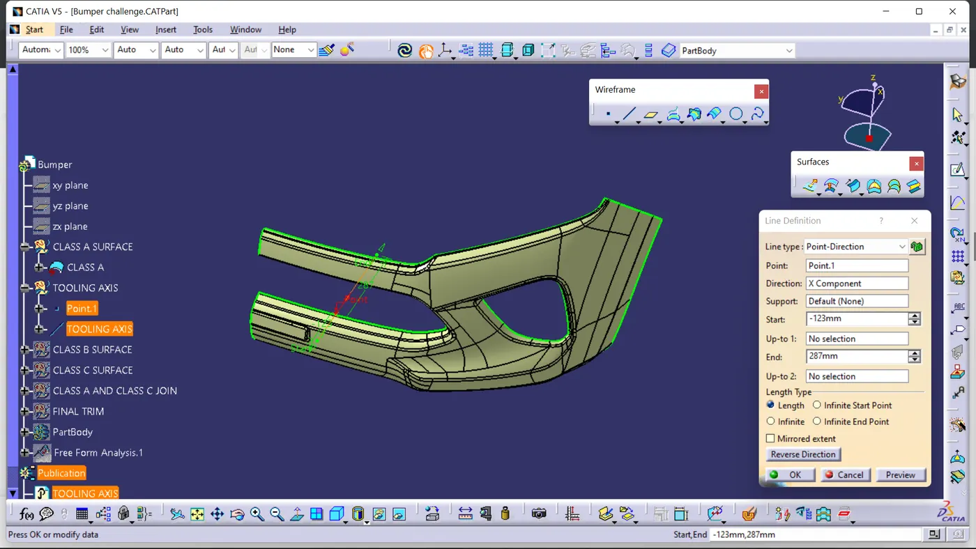
- do draft analysis along the Created Tooling Axis. if result Showing positive draft to Tooling axis then proceed or change Tooling Direction.
CLASS B SURFACE CRAETION:
- To create Class B surface, I have Taken offset surface by 3 mm To the Class A surface. but in offset surface was missing. that misssing sufaces created by using Multiple extract, Boundry, Extrapolation, Trim, Split and join Command
CLASS C SURFACE CREATION:
- one set of Class C surface are in the Tooling direction to the surfaces which are perpendicular to tooling Axis , and another set of Class C surface are created by using sweep with referance surfaces at 90 degree.
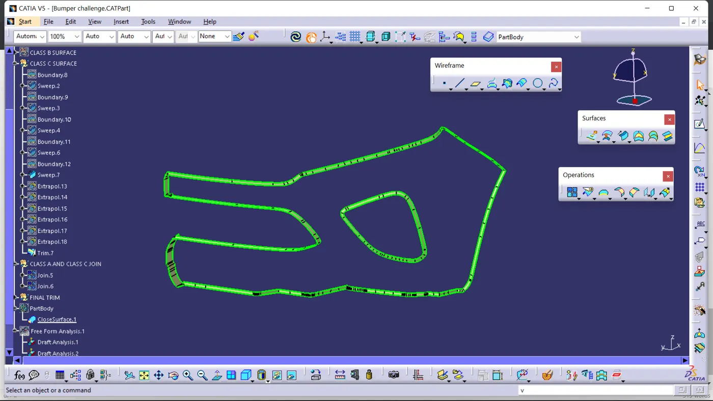
FINAL TRIM AND CLOSE BODY CREATION:
- joined Class A, Class B and Class C surface Together By using join and trim. and created close body.
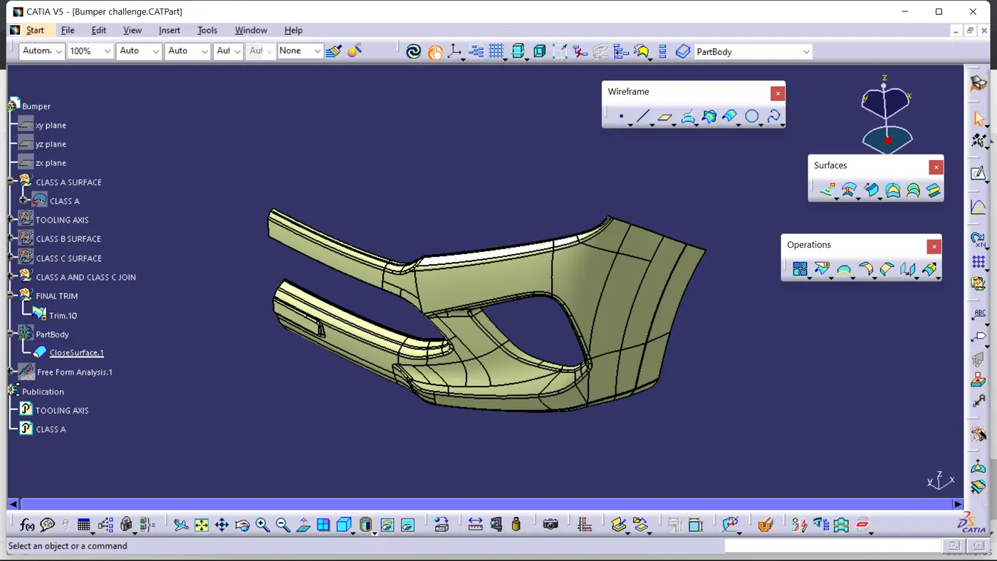
DRAFT ANALYSIS OF CLOSE BODY:
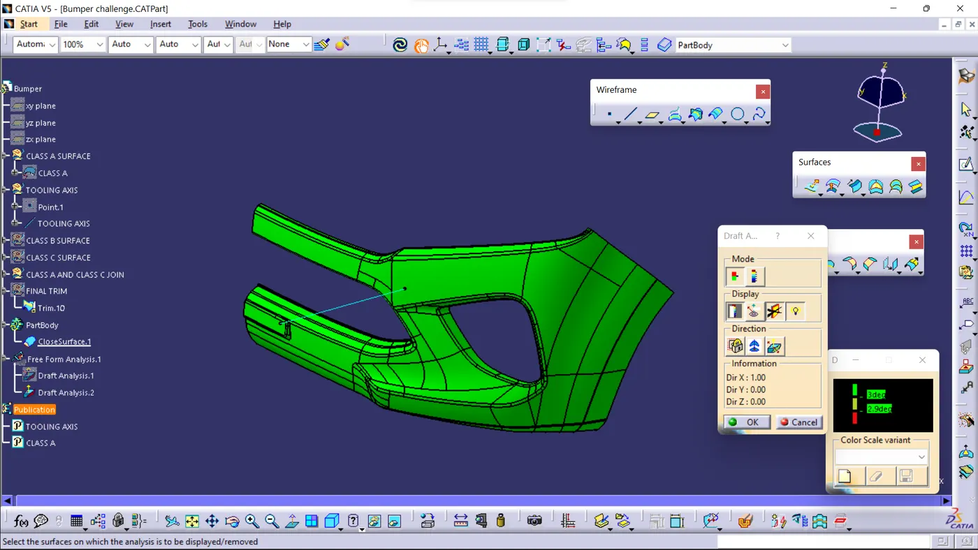
- the Draft analysis result is ok as all surface Class A having draft more than 3 degree.