Week 9 - Challenge 2 - Switch Bezel Design
SWITCH BEZEL DESIGN AND DRAFT ANALYSIS
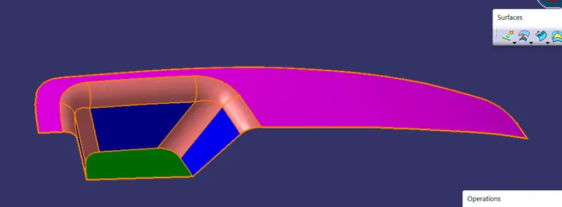
OBJECTIVE: Design of close body of swich bezel from class A surafce. The class C surface should be draft in 3 degree along the Tooling Direction.
INPUT: Class A Surface of switch bezel
DESIGN STEPS:
- Tooling Axis Creation.
- draft analysis of class A Surafce along Tooling direction.
- Class B surface Creation by creating Offset Surfaces.
- Class C surface Creation by Sweep with draft direction.
- create final Trim surface by join and trim.
- create close body by Close surface and do Draft analysis
Design Procedure
1. CREATION OF TOOLING AXIS
- first we have to check the irregularity in the Class A surface, by using boundry or join command.
- select the tooling direction such that all class A surfaces should Clear in Tooling direction. here we select the Z Direction.
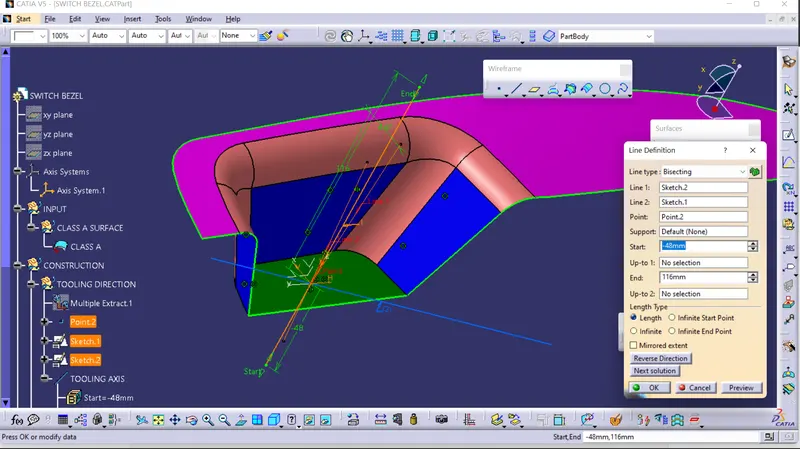
- extract Bottom surface, create point on extracted surface, Instead of create plane create new coedinate system on that point, take interection of Class A surface on xz plane, create two lines on xz plane along intersection of two side walls, and create bisection line to that two lines.
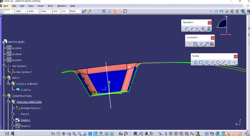
- we can clear only two side walls by using this axis as a tooling axis. we have to make tooling axis for x direction also.
- create sketch in xz plane ,take intersection of Class A surface, draw a line inclined to the line which created on intersection. give a incline angle 4.5 degree.
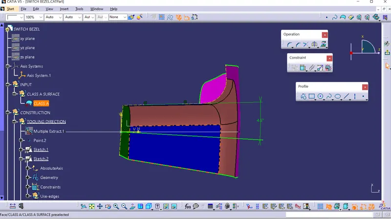
- here we have two line for tooling axis one for two side plane and another for third side plane. so create tooling axis by bisecting them.
2. DRAFT ANALYSIS OF CLASS A SURFACE
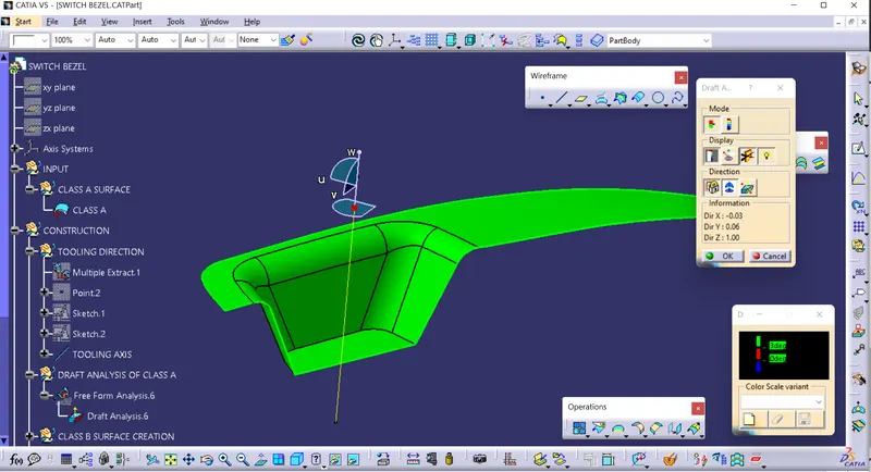
- do the draft analysis of class A surface by Tooling Axis. minimum draft to be 3 degree. check draft angle and go ahead or edit to tooling axis. And After that Publish The Class A surface and Tooling axis.
3. CLASS B SURFACE CREATION
- let divide the Class A surface into parts, so it will become easy to next operation step by step. let consider Bazel rest surface, Walls, Base and fillet.
- Extracting bazel rest surface,three Walls and base surface. untrim them and extrapolate them. doing one by one for one surface set.
- create the offset surface to the Class A surface by 2.5 mm. offset it in oppposite direction of Class A surface side.
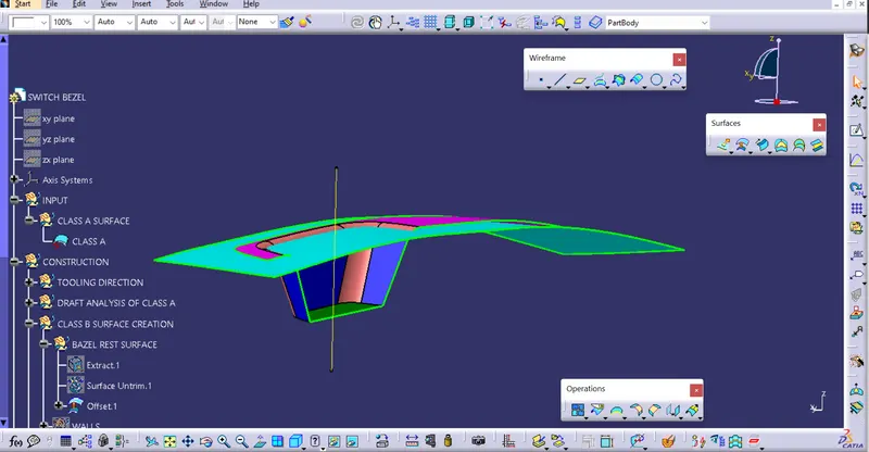
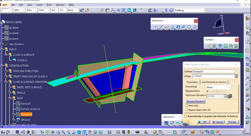
- Trim all Offsetted surfaces and create Final trim of B surface.
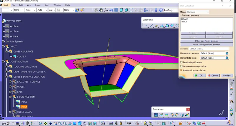
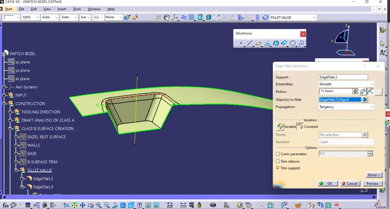
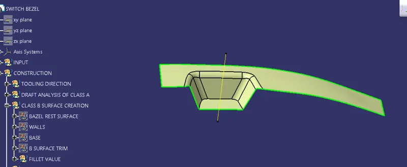
- we do not offset the fillet surface, fillets make complex process. so create the fillet to b surface trim. fillet value should such that part to be with uniform thickness.
4.CLASS C SURFACE CREATION
- To create Class C surface along Tooling direction through the outer boundry of Class A surface, we have to extract the outer boundry by extract or boundry command. we will extract outer boundry in two parts.
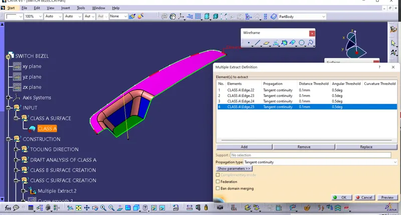
- now make smooth to extracted boundry , so it will create smooth pach surface
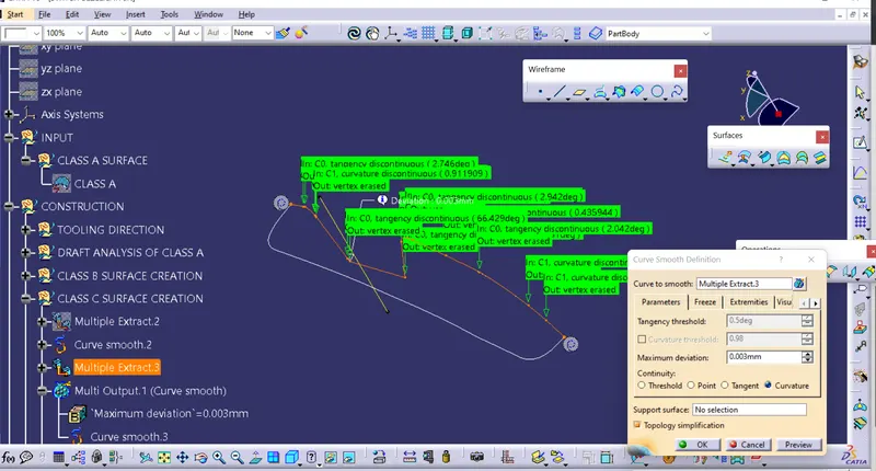
- now Draft the extracted surface along tooling direction with 3 degree draft, choose outside direction to draft so parting line will come on B surface side.
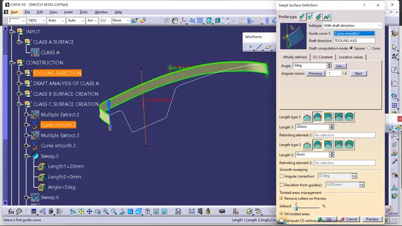
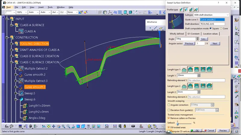
- now extrapolate the sweep surfaces and trim them, then single class C trim surface will create.

5.CREATE FINAL CLOSE SURFACE
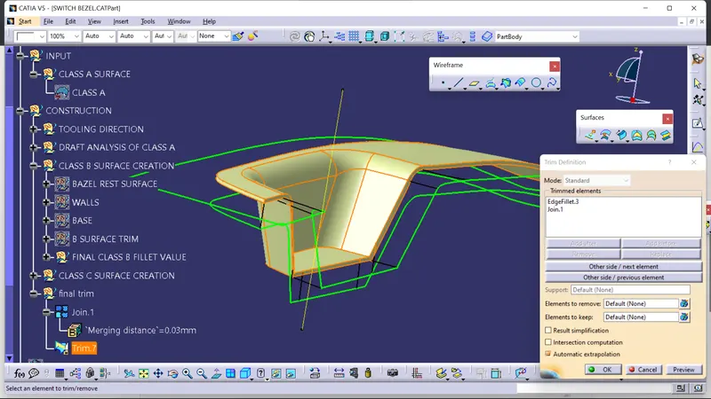
- now join the Class C trim surface (Trim 5) with the Class A surfece with merging distance 0.003.
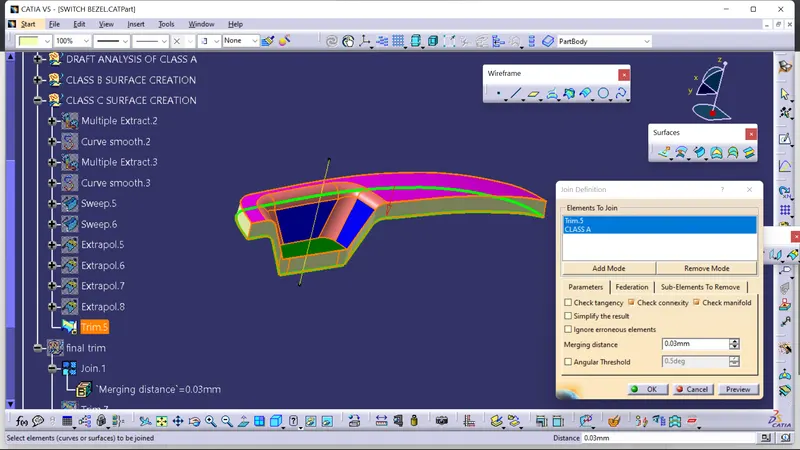
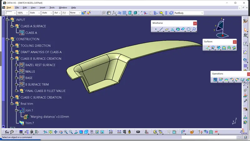
- now trim this Joined surface (join 1) with Class B surface.
CLOSE BODY AND DRAFT ANALYSIS
- now check the this surfaces is close, having not any open edge. Now create the close Body
- apply material mesh in view mode customisation parameter. and Create close surface by Close surface Command.
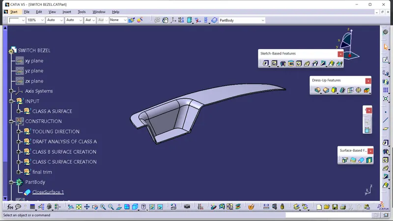
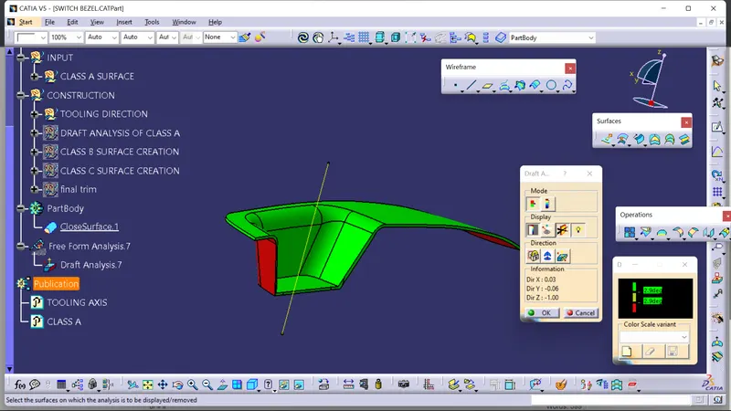
- here i do Draft analysis by Tooling axis At an angle 2.9 degree.