Week 10 - Challenge 1- Attachment Feature Creation (Ribs & Screw Boss)
WEEK 10 CHALLENGE 1 : Attachment Feature Creation (Ribs And Screw Boss)
INPUT: Class A style Surface of Drill handle.
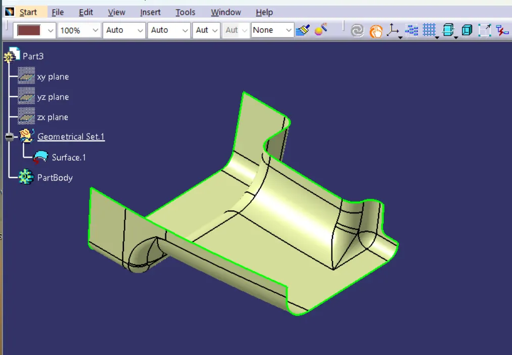
Design Procedure:
-
Tooling Axis Creation and Draft Analysis on Class A surface.
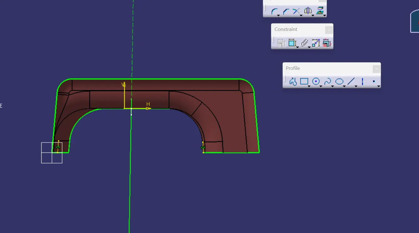
To Create Tooling Axis, see Componenet from all direction, select the direction such as all class A surface should cleared in Tooling Direction. here i select Y direction. taking the intersection to xy plate of Class A surface and creating Dummy Tooling Axis.
Did draft Analysis of Class A surface from Tooling Axis, here i get Result of Draft Analysis is ok as all faces having draft greater than 3 degree except 2 surfaces have draft of 1 degree. we can ask to class A style engineer to provide with draft.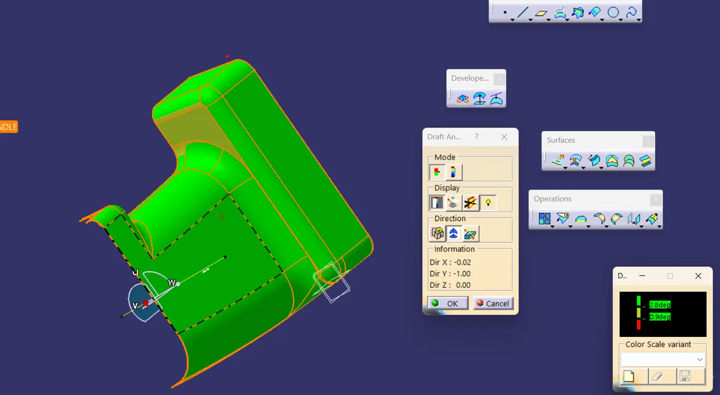
- Class B and Class C Surface Creation.
Created the Class B surface by Offsetting the Class A Surface. correct the surface by creating patches which is missing after offsetting the surface. join them and extrapolate them.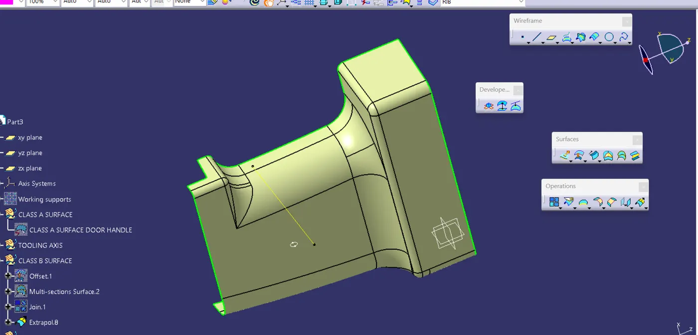
Created Class C Suraface by two methods.
A) sweep with draft direction : the Class A surface which nearly perpendicular to tooling Axis, Class C surface should with Draft angle 3 degree to tooling Axis.
B) sweep with referance Surface: the Class A surface which having parallel to the tooling axis, that respective Class C surfaces created by sweep with referance surface with 90 degree angle.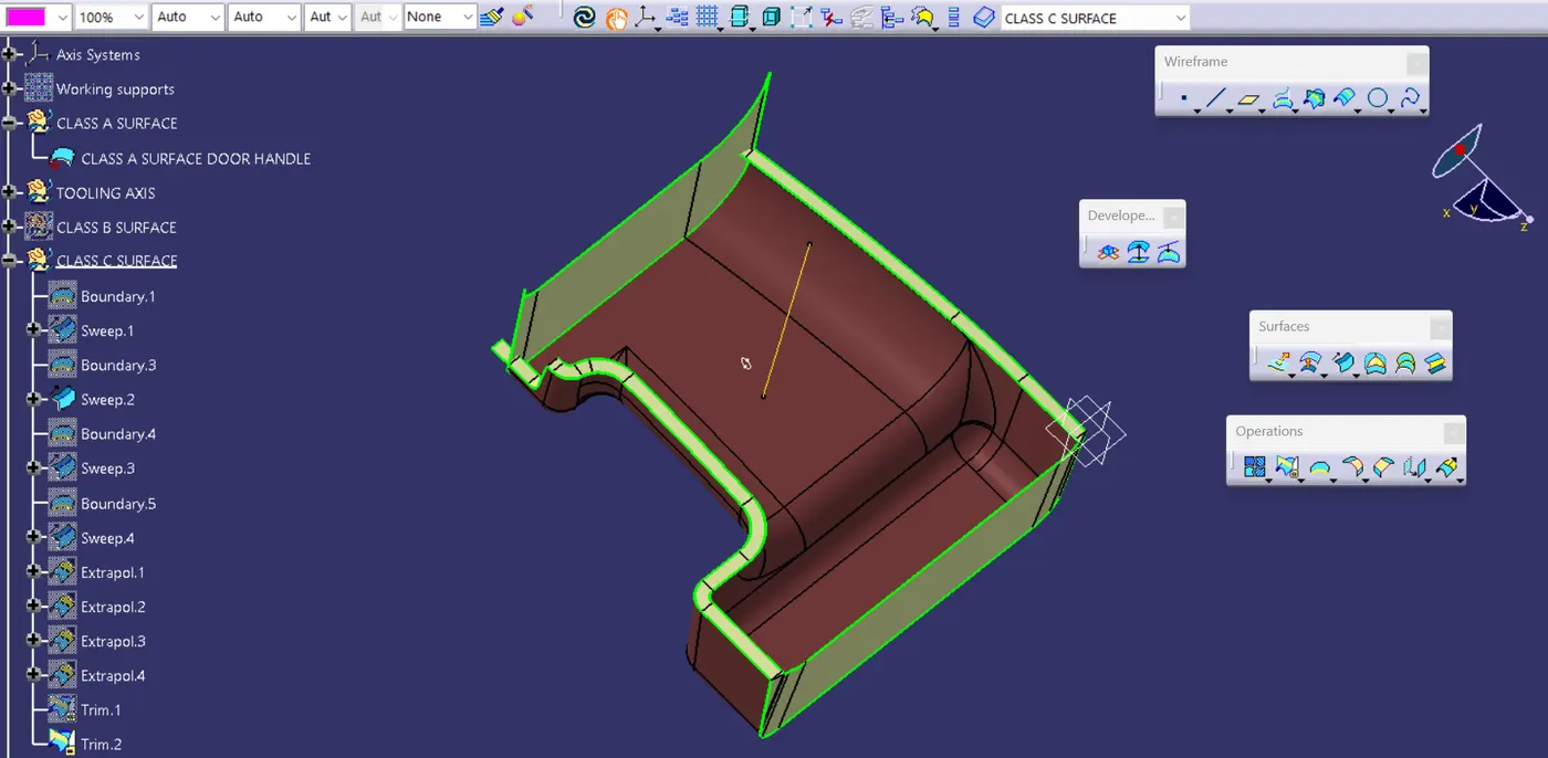
Trimed Class B with Class C surface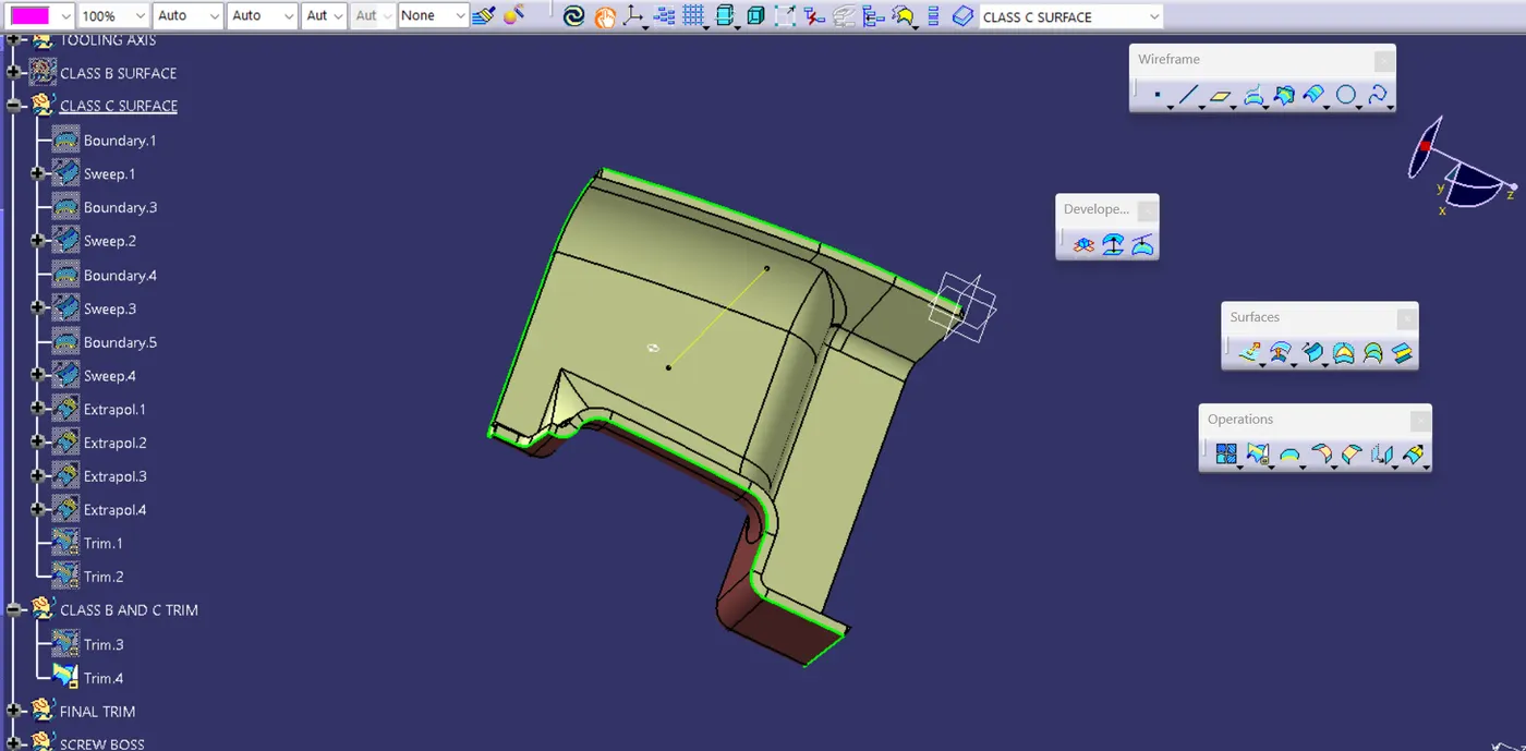
joined Class B and C trim with Class A surface -
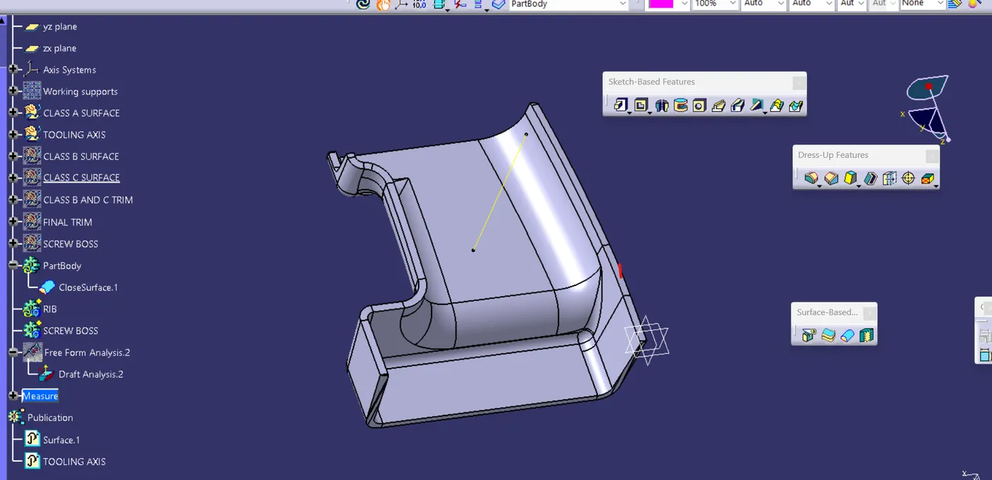
Closed Body Cration.
Formed Close Body From closed Trim of Class A, Class B and Class C surface.
-
Screw Boss Design.
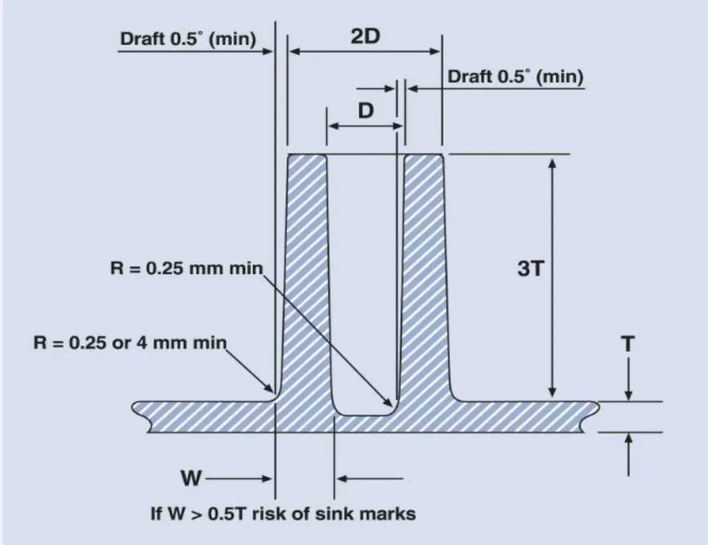
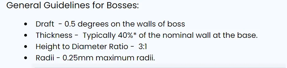
considering The Bolt Size of M6, hole ID is taken 5.2 and od as per Rule of 40% of wall thickness 5.2+0.4*2=7.2 is taken and Boss Height 3*2.5=7.5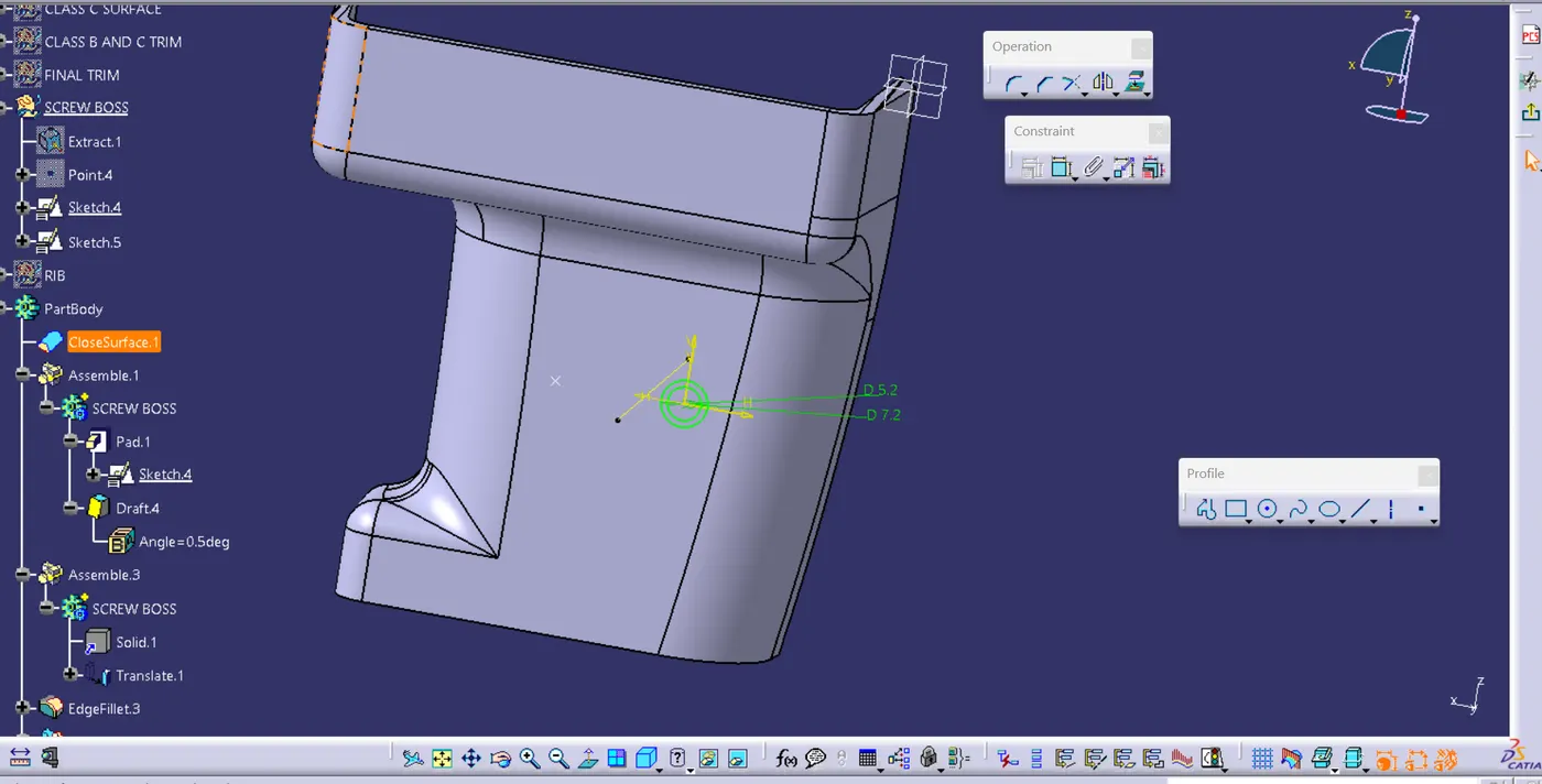
assembled boss on main body, made a copy of boss and given draft of 0.5 deg and fillet of 0.25.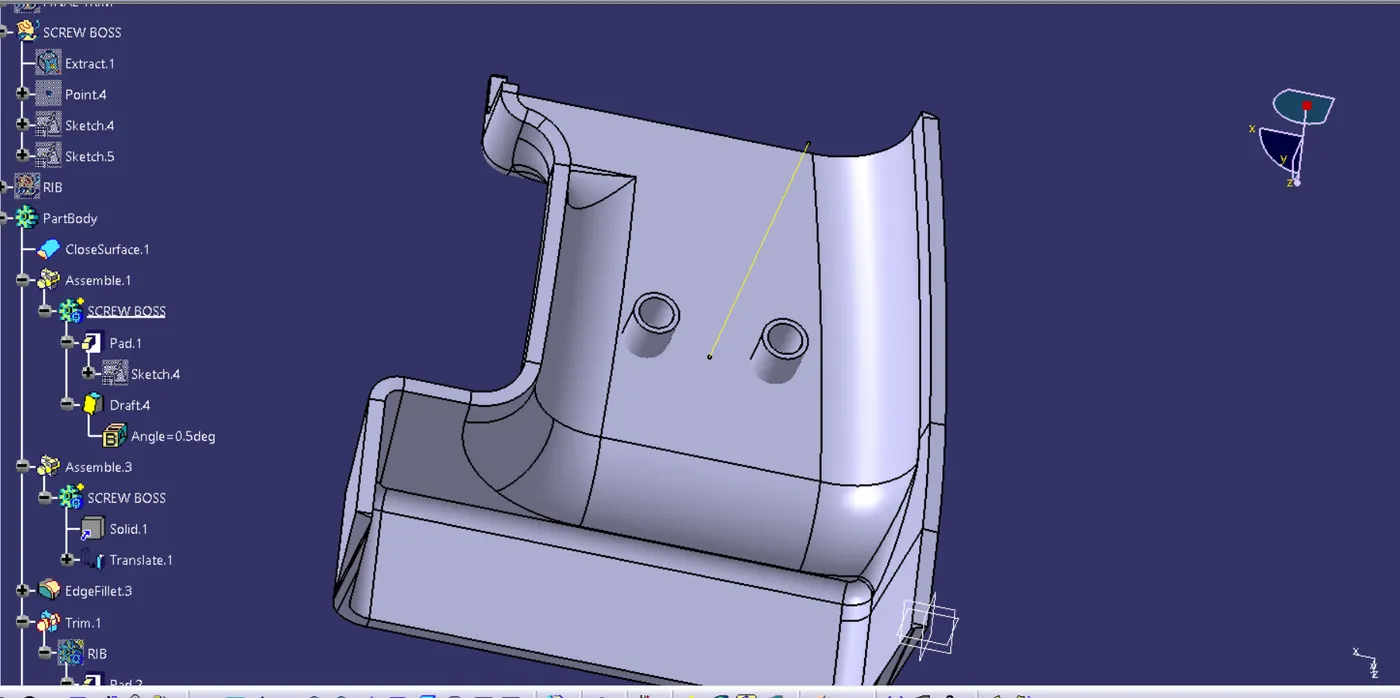
-
Rib Design and Rib Root Thickness Analysis.
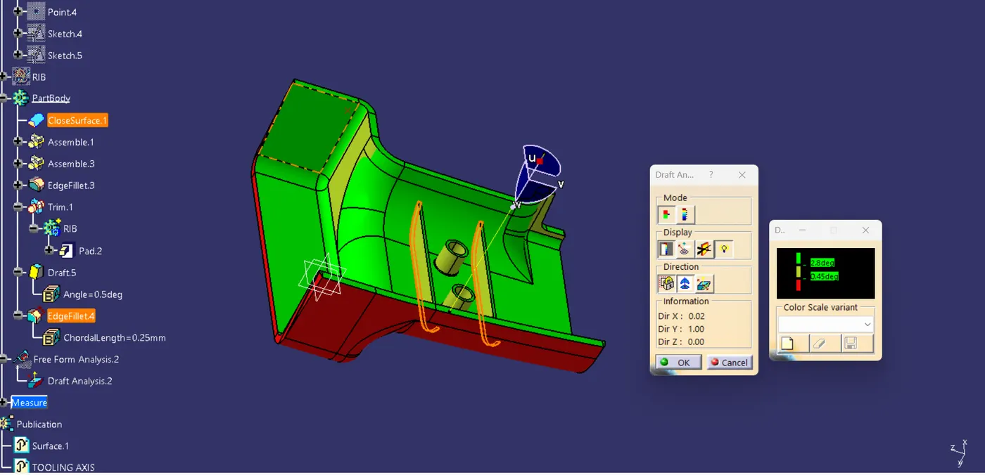
Drawn Two lines on Class B Surface of Door Handle to etrude Ribs. extruded The ribs 7.5 mm as per rule and given thickness of 1 mm as rule of 40% of thickness of base thickness. Given draft of 0.5 deg and fillet of 0.25 mm. and assembled Ribs on main body.
 .
.
as per rule Rib Root Thicknes sdeviation are Within 30% of Rib Thickness.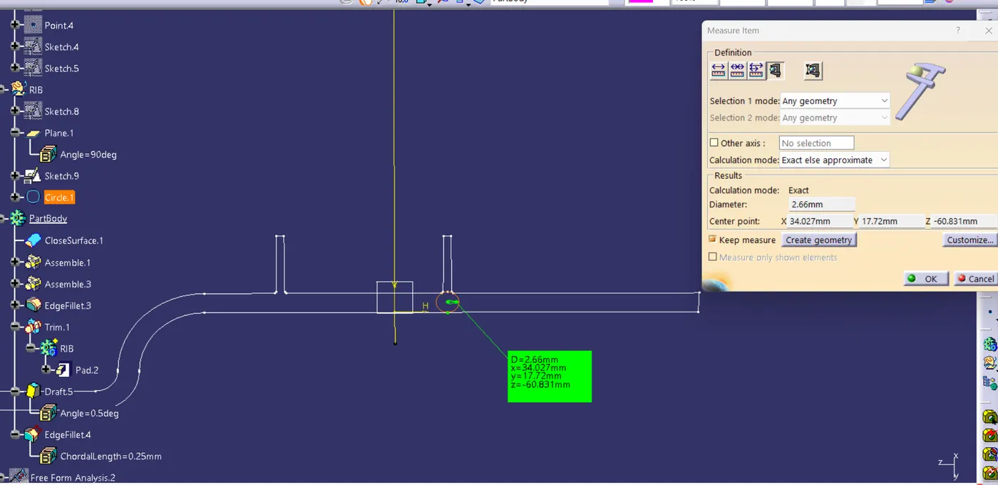
-
Draft Analysis on Final Component.