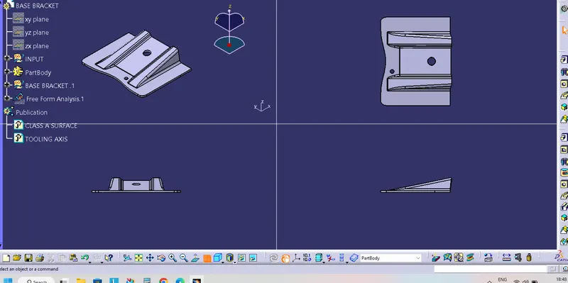
Week 9 - Challenge 1 - Base Bracket Design
Aim: To create a Base Bracket Plastic Component through a given Class A Surface and perform Draft Analysis on the final plastic component.
Objectives:
- Creation of Tooling Axis.
- Creation of Class B and Class C surface.
- Creating a solid part out of surface modelling
- Draft Analysis of Class A surface and final plastic component.
Tool Used: CATIA V5
Introduction: In this project we are designing a base bracket using given class A surface. The approach includes creation of Class B surface keeping 3 mm thickness in mind for the complete component. The design also included Class C creation from the given parent surface.
Constraints:
- NO CHANGES IN CLASS A ARE ALLOWED.
- PART THICKNESS CANT DEVIATE BY MORE THAN ±±30%
- ALL DESIGN RULES SHOULD BE STRICTLY FOLLOWED.
- ALL SURFACES SHOULD BE CLOSED BEFORE CONVERTING TO SOLID.
- ALL FACES SHOULD MEET THE ALLOWED DRAFT REQUIREMENTS.
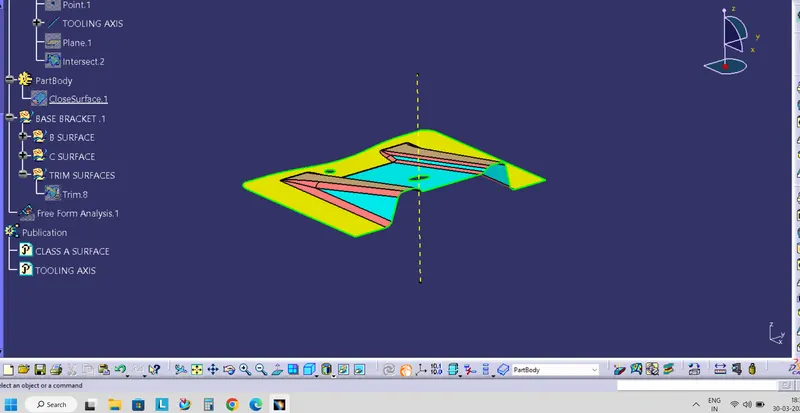
STEP 1:
Check the connectivity of the Class A Surface
Ensure that there is no gap between the component, using the join command.
We can visually check it or by clicking the boundary command.
It has 3 boundaries one outer and two inner circle boundaries.
Therefore first check was completed.
STEP 2:
Find the tooling axis of the component. The tooling axis is nothing but the mold opens or the cavity opens.
Check visually which is the best possible tooling axis.
Check all three axes.
Along x it is possible but expensive and y is not possible.
z is the best possible tooling axis
Class A is the surface that is created by the concept sketches made by free hand sketchers. The finalised sketch is then fed to the computer and a 2D surface is created out of it by the use of a software like Alias. This computerized design is known as Class A surface.
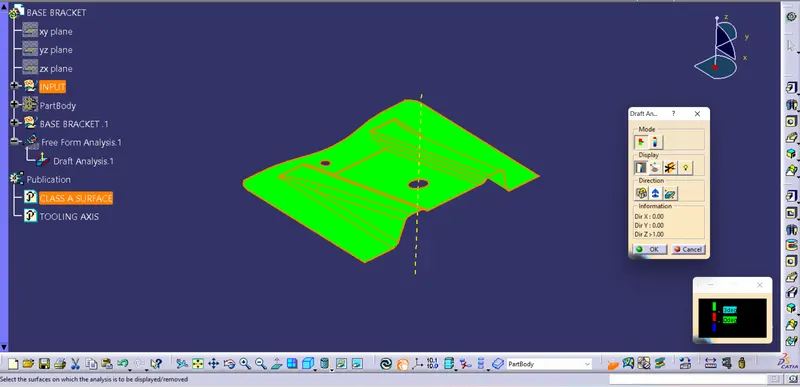
Class B is a reference surface that is created by the design engineer and is a copy of the class A surface that is at a distance equal to the thickness of the part.
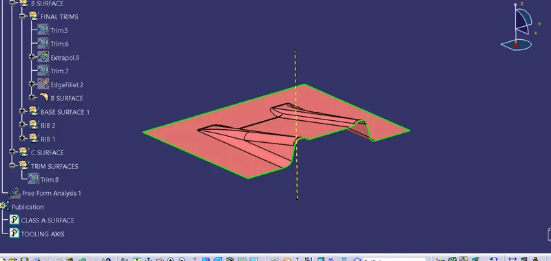
Class C is again a reference surface that is created by the design engineer to connect Class A and Class B surface also known as the side wall of the surface.
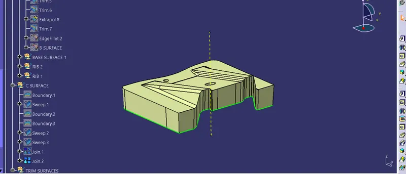
Class A + Class B + Class C:
For this we have trimmed the above shown surface with the Class B surface using trim feature.
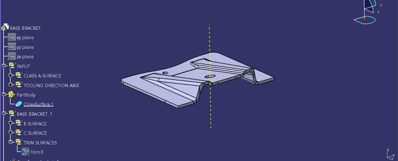
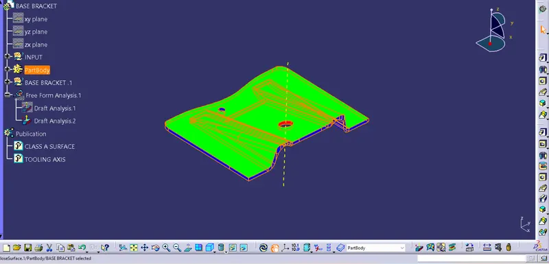
VIEWS: