Week 9 - Challenge 1 - Base Bracket Design
-------------------------------------------Base Bracket Design-------------------------------------------
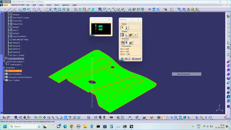
- Class-A surface Draft analysis
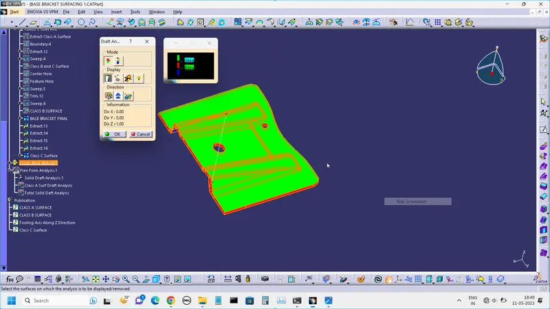
- Solid Part Draft Analysis
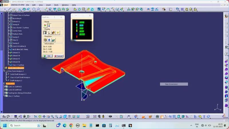
- Total Draft Analysis of Solid Part
- various orientations (Isometric, Front, Side, and Top View)
Front View
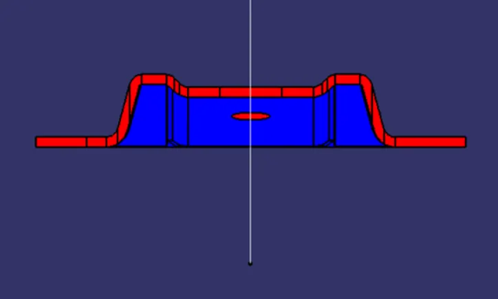
Side View
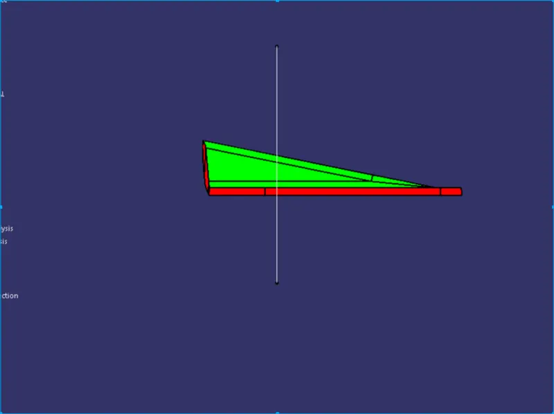
Top View
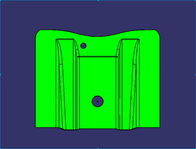
Isometric View
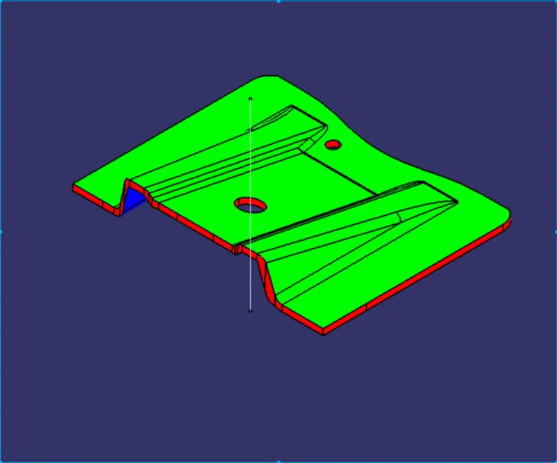
- Report
1. Tooling Axis Creation
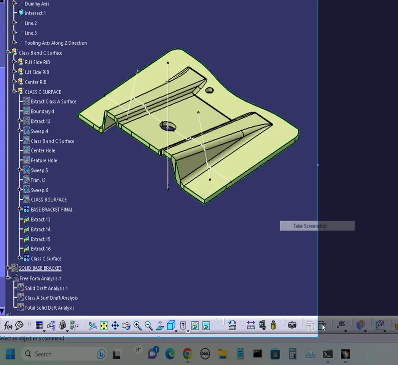
- Take the class A surface
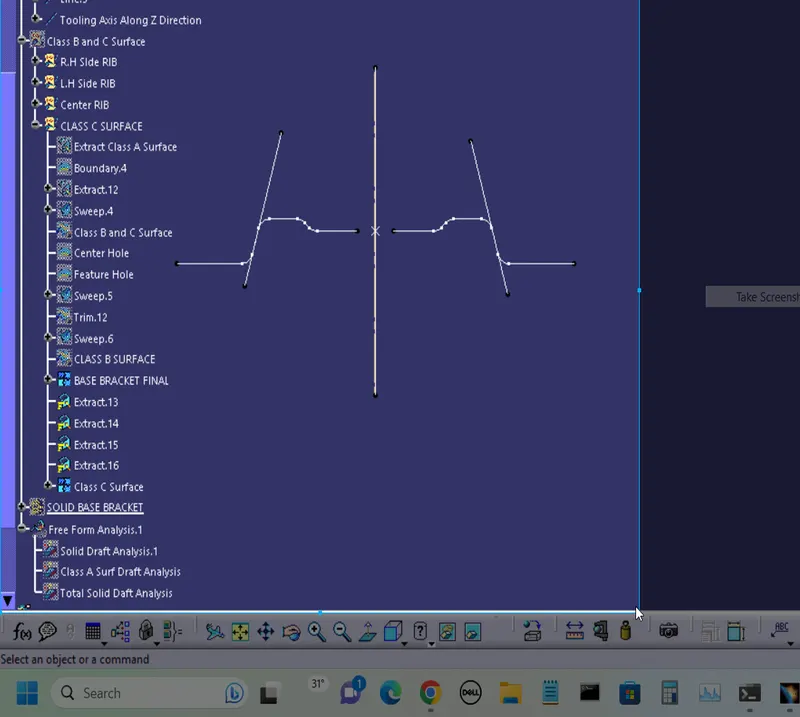
- Select the centre hole and create the Origin Point
- Choose the Line command and make the axis which will pass through the centre of the Hole.
- Choose the Intersection option
- Click the pane on which intersection line to be projected then touch the class A surface.
- click line command (point to point) and touch both sides of 2 points which makes the draft angle then extend in bi-direction.
- Choose the Line command then go for Bisection Method
- Click both side lines and then touch the Origin.
- A centre line will create which will describe the Tooling direction of the tool with respect to Draft.

2. Draft analysis
- Select the Feature Draft Analysis
- click the part and define the tooling Direction
- Green Side is showing that the part will be made according to the Draft Angle which is 3 degrees and there will no erosion between the Tool and Plastic parts.
- The red side is showing the Draft angle as 0 degrees and the part will erode with the tool.
- The blue side is showing a negative Draft angle (interference) or is impossible to draw the part according to the draft angle.