Week 9 - Challenge 1 - Base Bracket Design
AIM:
With a given Class A Surface, the objective is to produce a Base Bracket Plastic Component. The plastic component will then undergo a Draft Analysis.
OBJECTIVES:
- Creation of Tooling Axis.
- Creation of Class B and Class C surface.
- Creating a solid part out of surface modelling.
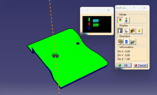
- Draft Analysis of Class A surface and final plastic component.
GIVEN CLASS A SURFACE:
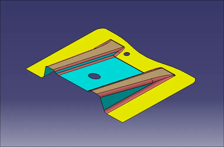
To continue with the design process first we need to find out the tooling axis for the surface and check for all the drafts using Draft Analysis tool of CATIA.
DRAFT ANALYSIS
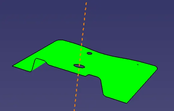
CREATING OF TOOLING AXIS:
- Create an intersection of CLASS A surface with ZX plane and from the intersection create the tooling axis as shown below
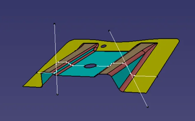
- Create a bisecting line using the lines shown above.
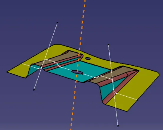
- Here, Line shown in dotted green is our tooling axis.
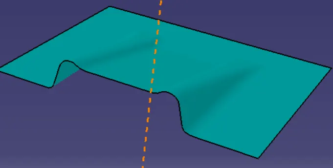
CREATION OF SURFACE B:
- In order to create Class B, we first removed the parent surface from Class A and then untrimmed it.
- The desired thickness is then offset onto these surfaces.
- After offset, each surface is cut to the desired shape.
- The surfaces receive the necessary fillets.
CREATION OF CLASS C:
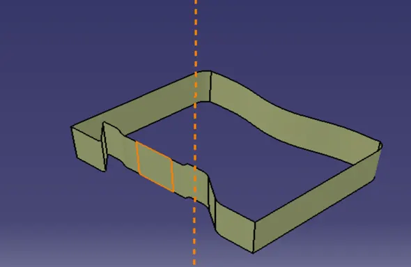
- We used multi-extract to extract the Class A boundary for this surface, which we then turned to a smooth curve.
- This smooth curve is now swept with a 3-degree draught along the draught direction.
FINAL TRIMS:
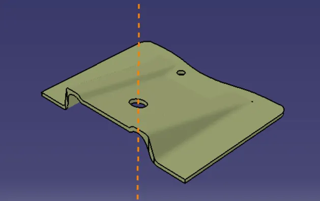
- Class A + Class B + Class C;
FINAL DRAFT:
Final view:
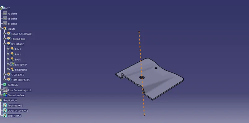
CONCLUSION:
Hence the base bracket design was successfully completed.