Week 9 - Challenge 1 - Base Bracket Design
Week 9 - Challenge 1 - Base Bracket Design
Aim:
To Create the Base Bracket Plastic component through the given Class-A surface and create the tooling axis and perform the draft analysis to the class A surface and Final plastic component.
Objectives:
- First create the tooling Axis.
- Analysis the Class A surface, if you got any mis-match surface reconstruct the Class A surface.
- To create the Class B & C surface
- Create the solid part and ensure the close surface.
- To perform draft analysis on the final plastic component.
Class A surface:
Class A surface is the asthetic curvature surface which is represent the main component skin data. Before proceed the Class A surface analys the class A surface have any mismatch curvature.If got any mis-match surface reconstruct the class A surface and then proceed to create B surface.
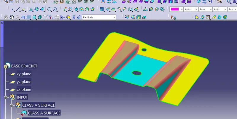
TOOLING AXIS:
TO analys the class A surface first create the Tooling Axis, the tooling axis is tends to the core and cavity direction. So the tooling direction is defined to the component ejecting direction.First create the plane perpendicular to the core and cavity area. Then draw the intersecting line on the Class A suface.
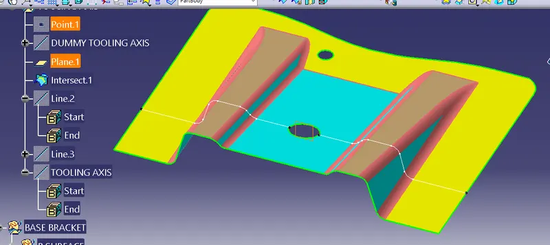
Dummy Tooling axis
First of all create the dummy tolling axis for refence to the give Class A surface at the specific point.For creating dummy tolling axis pick the Point-Direction option at the reqiured direction.
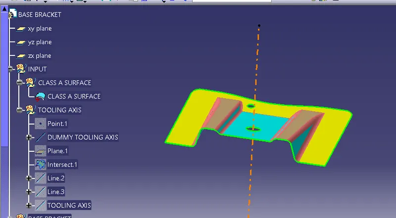
Once create the dummy tooling axis, create the Bisecting line on the intersecting boundaries.
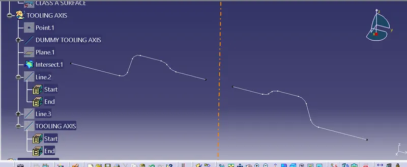
Before create bisecting line need the support line, so create the support line by the Point-Point option, pick up the vertex point on the both sides and define the supporting line.
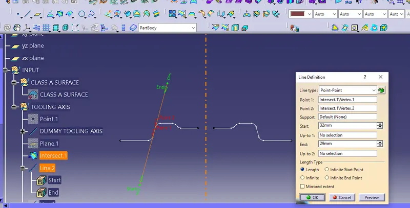
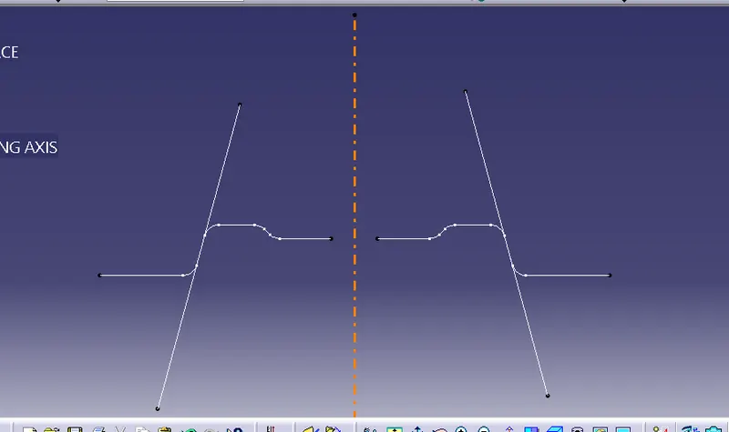
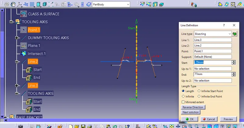
Bisecting Line => Line -> Line Type -> Bisecting Line
Tooling Axis created by the Bisecting Line and define the direction by the changing Next Solution. Hence the Tooling axis created successfully.
Draft Analysis Class A Surface
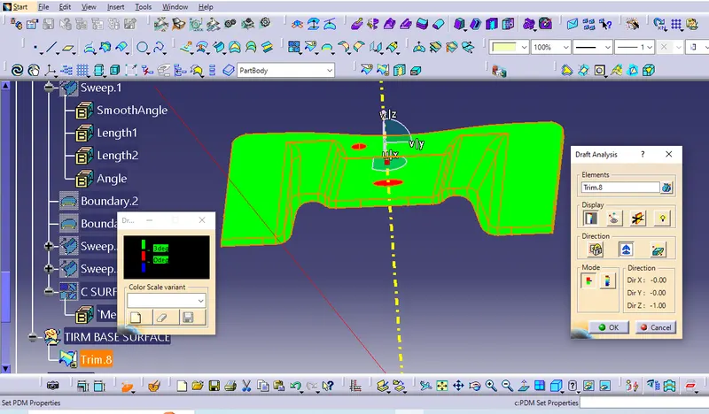
Draft is the main requirments in plastics molding. If the draft angle is less than 0 degree, the part or component and tool is to be damaged in mass production. So the drafting analysis to find out the lesser angle are by the colour variation.
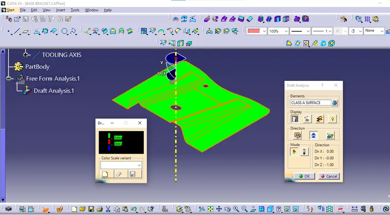
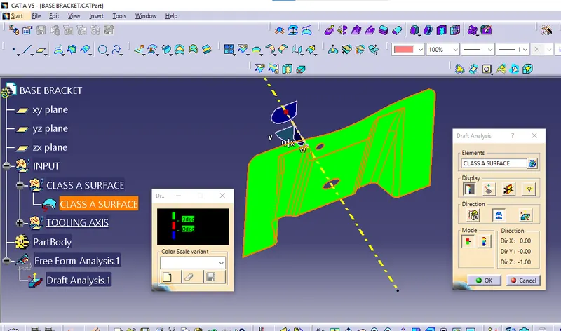
Above 3 - Green
0 to 3 - RED
< 0 - Blue
Class B Surface
To crate the Class B surface by using the class A skin data and extract the class A surface. In this
base bracket design the RIB area is going to be extract on both side and create the RIB areas.
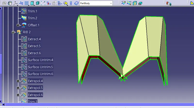
- Offset the base at the tickness of component (Thickness is 2.5 mm), Then the Extracted surface is Untrim and Extrapolated for the reqired B surface creation.
- Then the base surface of the skin data also created by the same manners and trimed to the Ribs.
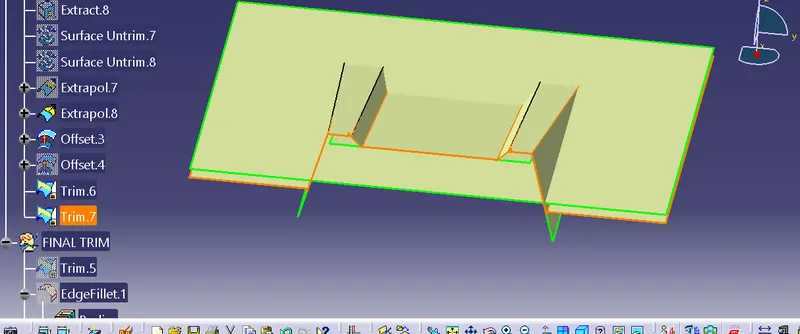
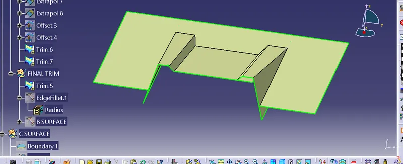
- After that the protruding extrapolated surface is trim and get the B surface
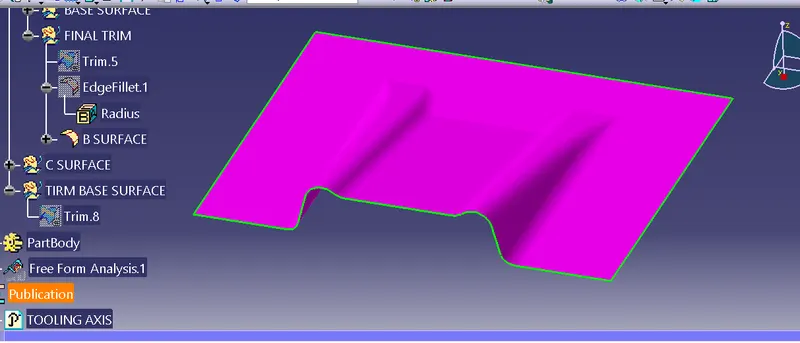
Class C Surface
To create a C surface Extract the boundary of B srfcae.
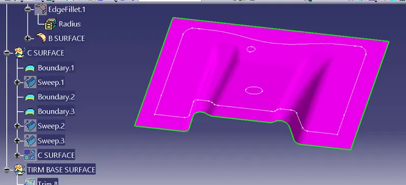
Then Sweep the boundaries to the Draft Direction at The tooling Axis support
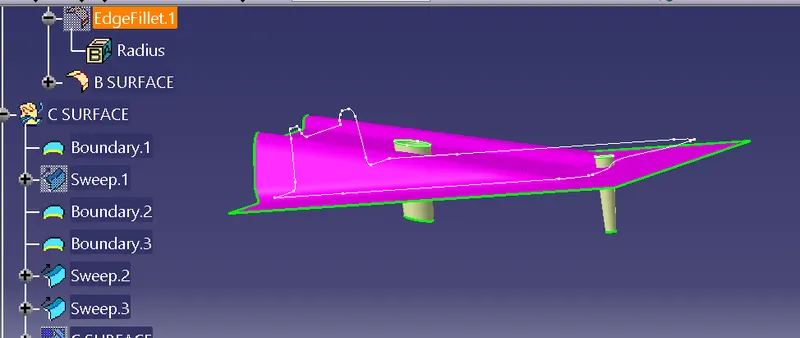
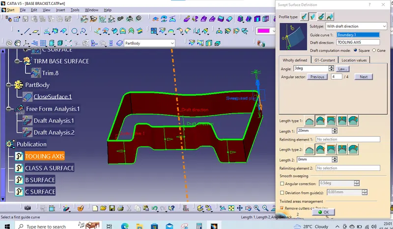
The class B surface boundaries are swept by the command Sweep at the drfat direction and tha angle is 3 degree.
Then Joint the Class A surface with the all sweep surface and got the C surface.
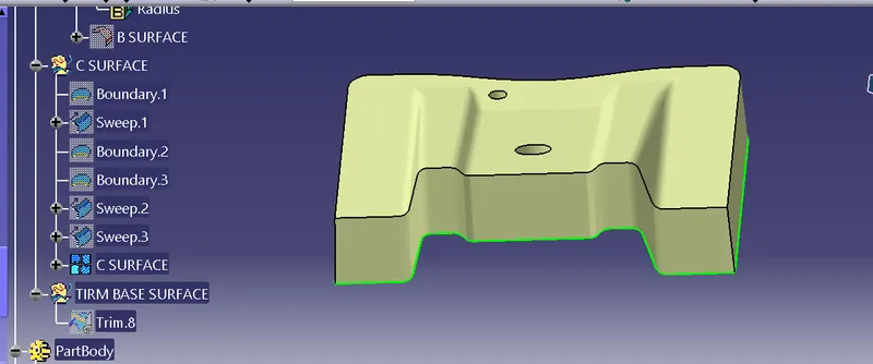
A+B+C Surface (Final Trim)
Finaly Trim the A+B+C surfaces and keep the component of require base bracket product.
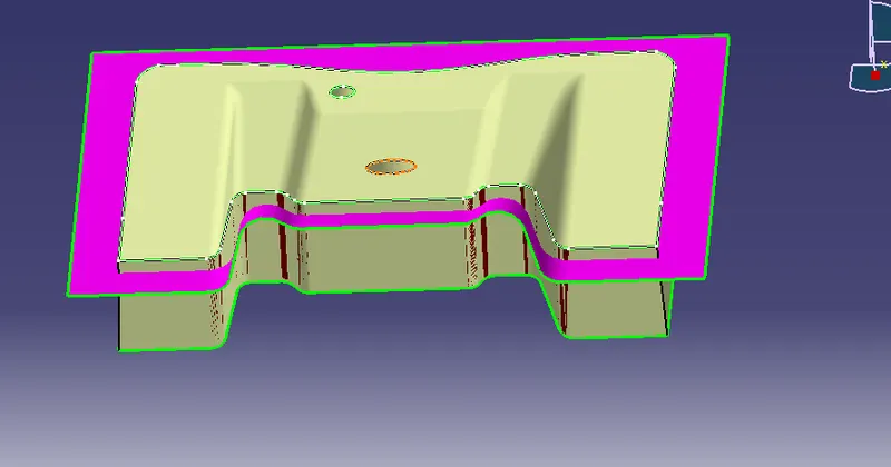
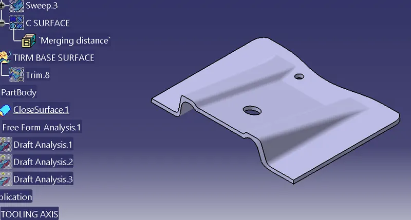
Final Brace Bracket
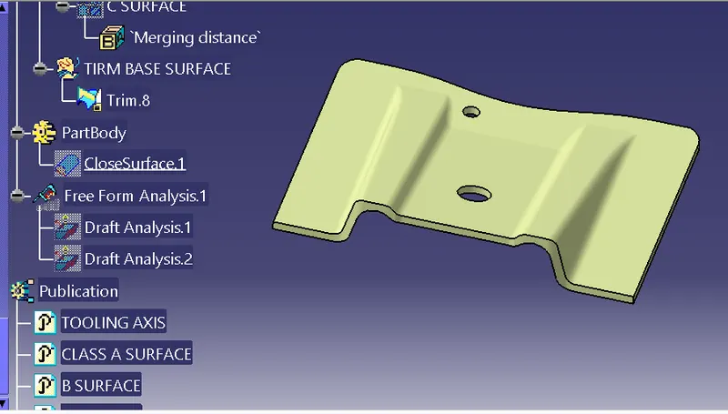
Final Close Body Draft Analysis:
Above 3 - Green
0 to 3 - RED
< 0 - Blue
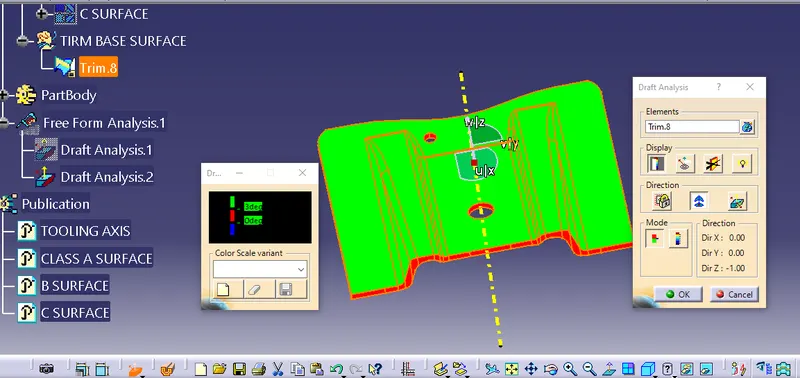
The Final draft analysis of the close body the edges showing red, so increased the swept of the B surface draft angle is 0.5 degree and again analys the drfat analysis is passed.
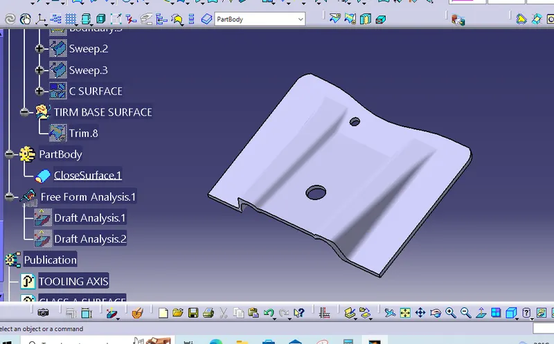
Close Solid Surface:
START -> MECHANICAL DESIGN -> PART DESIGN -> SURFACE FEATURE -> CLOSE SURFACE
FRONT VIEW
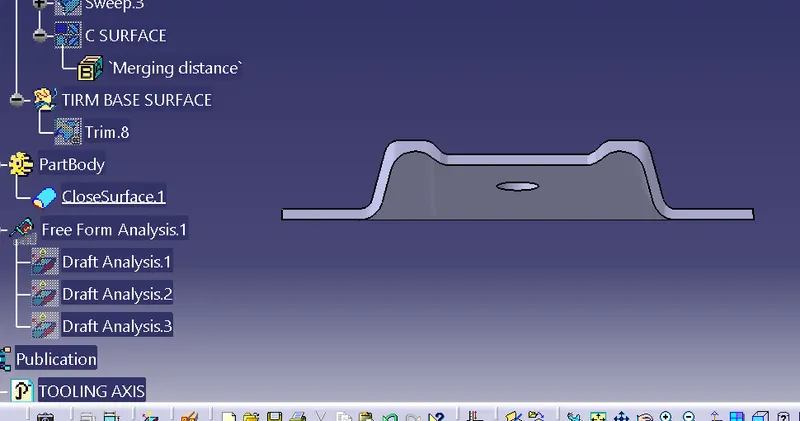
SIDE VIEW
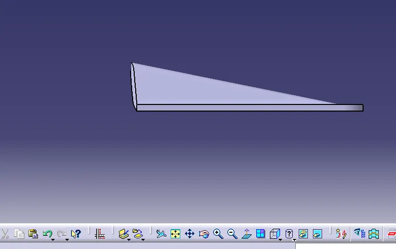
TOP VIEW
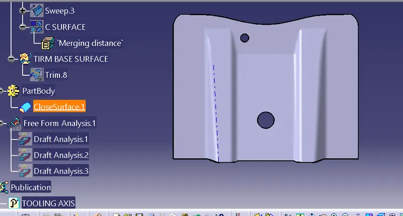
ISO VIEW
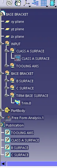
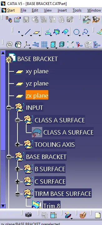
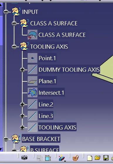
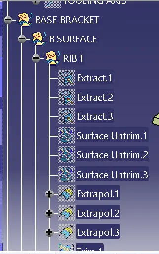
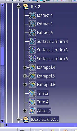
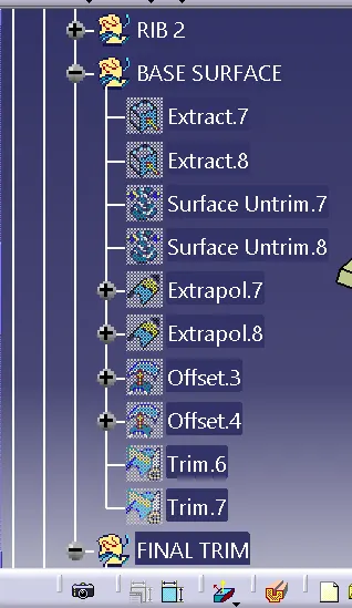
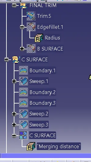
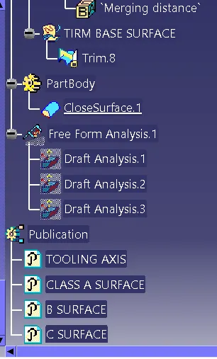
TREE STRUCTURE:
 CONCLUSION:
Finally the plastic component of Brace Bracket Design and drfat analysis was done successfully.