Week 9 - Challenge 1 - Base Bracket Design
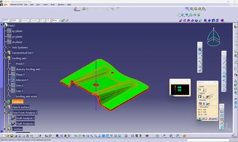
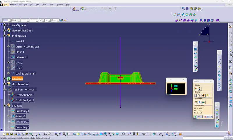
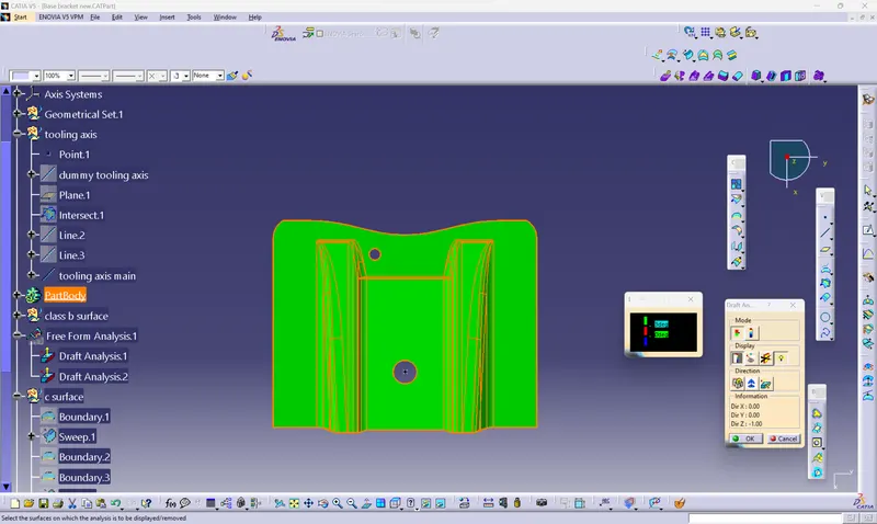
draft analysis
draft is 3degree and the draft is given to make sure that during the injection molding the part should be easily ejected
for draft we first creat the tooling axis and change the customized view parameter and pick the material the we do the draft analysis first we pick the compass and put it on the tooling axis and then lock it an then we click the display and click on the surface and change the green surface draft angle to max 3 degree
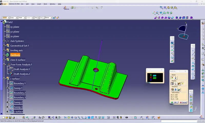
tooling axis
tooling axis is the axis in which the part should be removed and less use of side cores or lifters in this we find that the tooling axis in x axis is not possible as their is a hole on the upper side and in y axis their is also a hole on the plane surface so both x,y axis is not use
and for tooling axis we need a plane surface or a hole after that we intersect the palne with the surface and we increses the prallel line which is at some ange to the dumy tooling axis and bisect the two prallel lines with the point and choose the line which is parallel to the dumy tooling axis and the line we get is the main tooling axis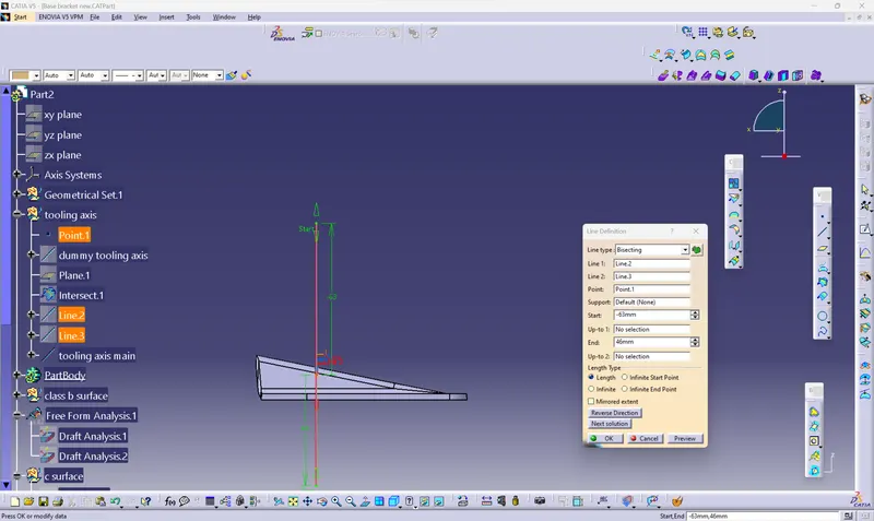
draft analysis report class a surface
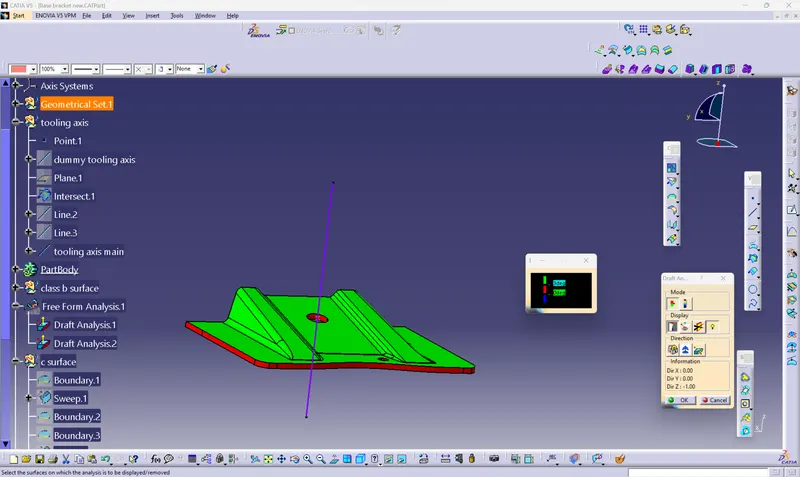
draft analysis final component
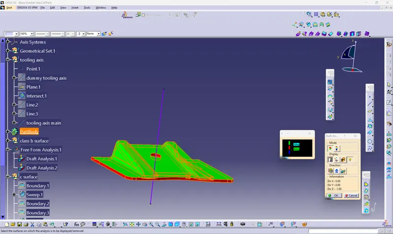
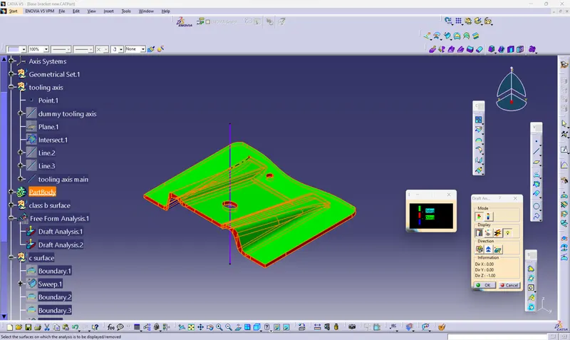
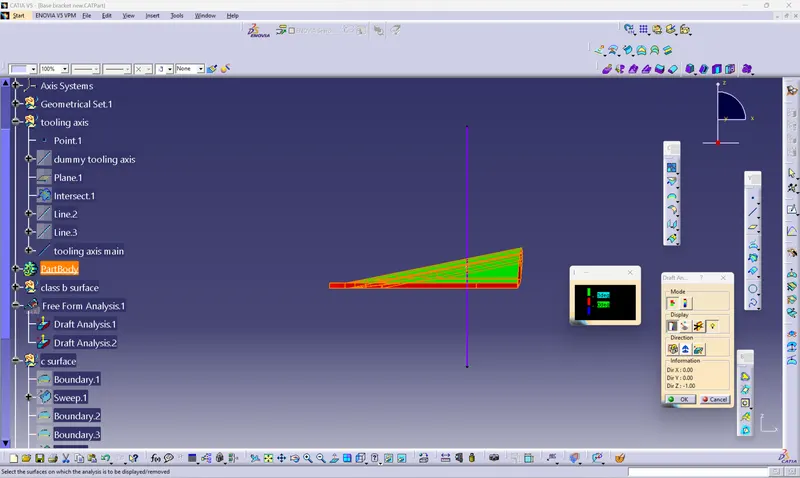
isometric,side, back,top
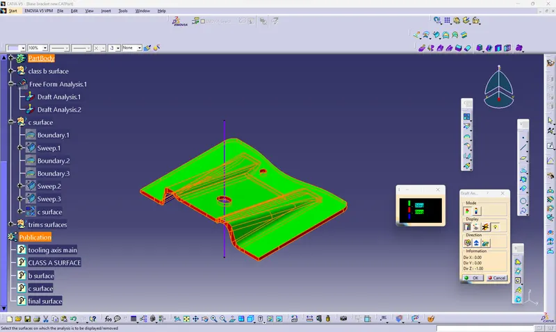
tree structure