Week 9 - Challenge 1 - Base Bracket Design
- Aim: Creation of Base bracket plastic component through the given Class-A surface.
- Objective:
- Learning how the Draft Analysis is done.
- Understanding the concept of creating a Tooling Axis.
- To understand how the tooling axis is created, particularly the Bisecting method.
- To know why the tooling axis should be created for a given class-A surface.
- Introduction: In this project, create a final thickened component by taking input as a class-A surface.
Giving a proper tooling direction for the Drafting axis of a component and Analysis of a class A surface.
Constructing step-by-step geometry to classes A, B, C, and Final components. Then draft analysis for the final product is done.
- Design methodology Flowcharts :
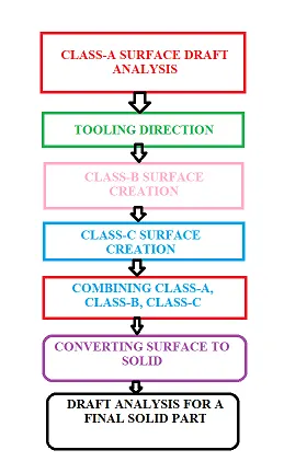
- Description for Draft Analysis: Here is the procedure followed to create this project
Firstly to create a final thickened plastic component of a given class-A surface, Import the class-A surface as input.
Giving a proper tooling direction for the Drafting axis of a component by creating Tooling Axis using Bisecting method,
we use the bisecting method to get an accurate and proper Drafting direction for the plastic component we made.
Drafting is done for each and every plastic component which is manufactured in the plastic and plastic automotive industries,
Drafting is done to eject the plastic component from the mold easily without any damage to the part and the mold.
To do analysis
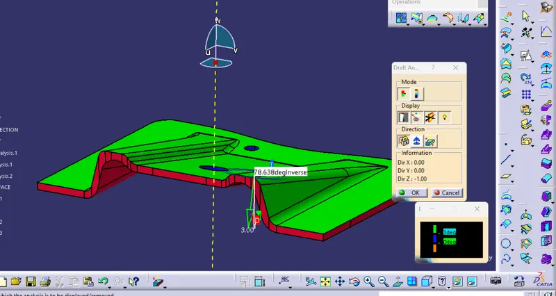
Give a material option in a customized view parameter go to Insert-Analysis-Feature draft analysis then you will get the draft analysis Taskbar you will see the below image
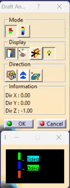
Now in the direction column click on the nob and place it on the tooling axis and then click on the lock button to lock it
then click on the surface of class A shown in the image below
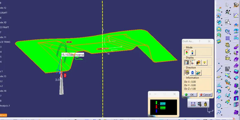
and then click on the display second icon analysis under the running point to do an analysis of the draft angle we got for a class-A surface
The color indication dialog box shows the maximum and minimum draft degree the top color indicates 0 to +1 above
and the bottom collar indicates 0 to -1 below. We can also change the draft angles and colors by double-clicking on them.
Views of the thickened plastic component
1) Front view
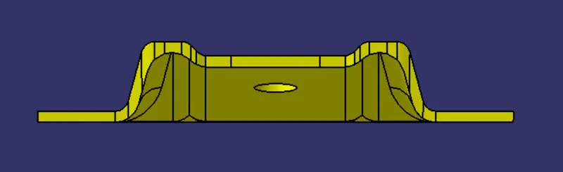
2) Side view
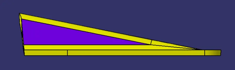
3) Top view
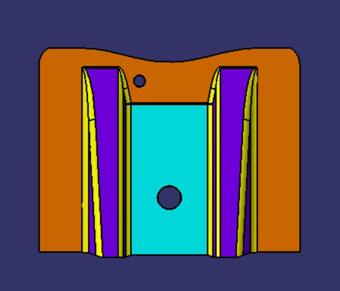
4) Isometric view
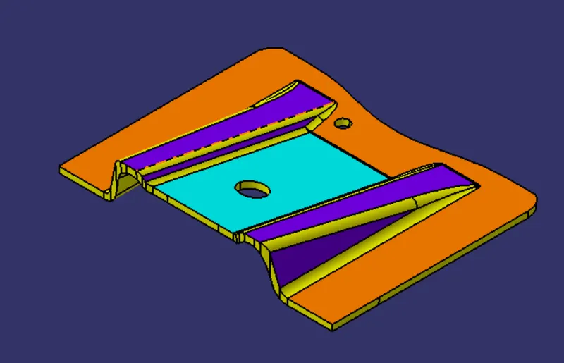
5) Final component Analysis
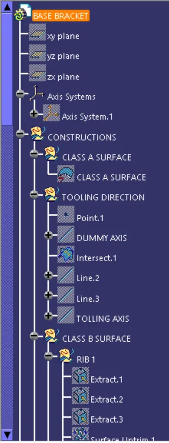
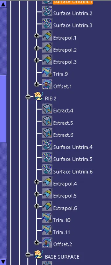
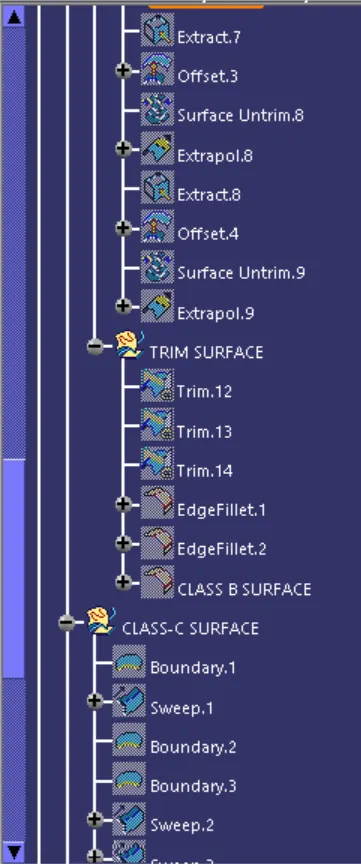
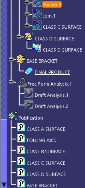
Tree structure
CONCLUSION:- Hence the draft analysis is done by creating a Tooling axis using the bisecting method.