Week 9 - Attachment Feature Creation (Ribs & Screw Boss) - Challenge 1
DOOR HANDLE ( RIB AND SCREW) DESIGN
OBJECTIVE:
Create the Plastic component for the Door Handle.
Create the Rib for the Handle considering the design rules.
Create the Screw Boss for the Handle considering the design rules.
INTRODUCTION:
First, Create the tooling axis and perform daft analysis on the class A surface. Then create the class B and C surfaces and join them together to get the plastic component and perform draft analysis on the close surface.
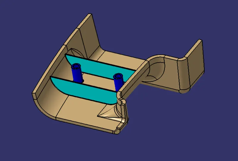
Create the Rib & Screw Boss on the B side of the close surface. Perform draft analysis on the final component.
CLASS A SURFACE:
Class A surface is an aesthetic surface with high quality finish. Most class A surfaces for an automotive component are made using Autodesk-Alias based on the final concept-sketch.
All class A surfaces should have Curvature-continuity which means the continuity between the surfaces should share the same boundary. It is taken as a reference by the Automotive Pastic Designer to create Class B and Class C surfaces.
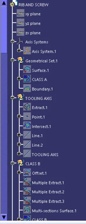
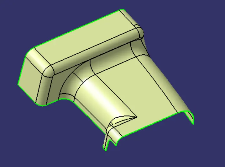
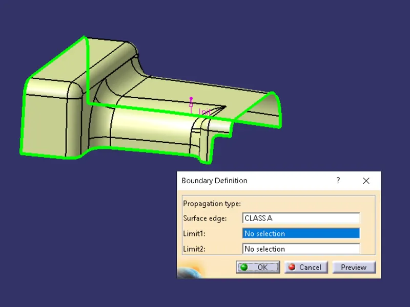
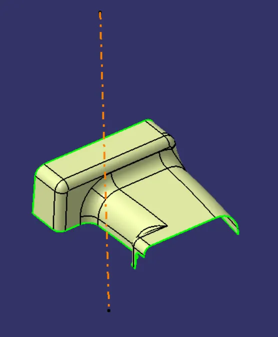
Import the given Class A surface, Check for continuity using boundary and create the tooling axis for the Class A surfaces and perform Draft Analysis.
TOOLING AXIS:
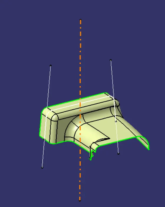
It is the direction in which the core and cavity opens and closes. After the class A is imported check for possible irregularity, using boundary.
Extract a flat surface, create a point on the flat surface using on surface option. Insert a axis system on the point.
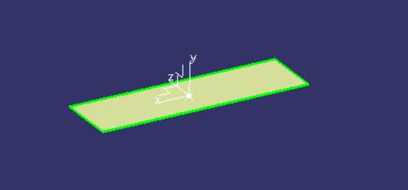
Do a Intersection operation between the axis system and the class A surface. Create two lines on the intersection points using point to point condition.

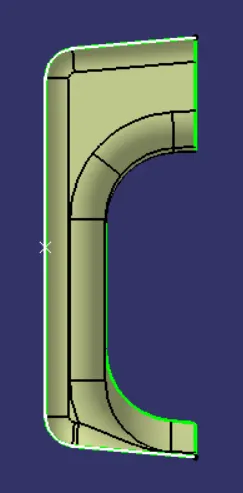
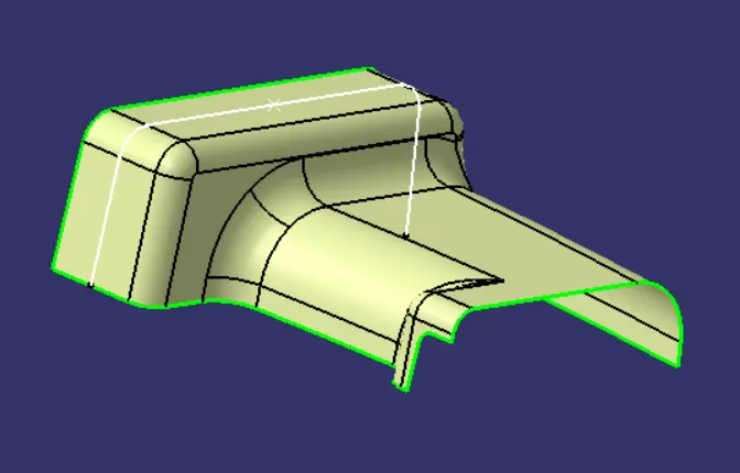
Bisect the lines using Bisecting method to create the Tooling axis.
DRAFT ANALYSIS:
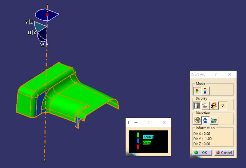
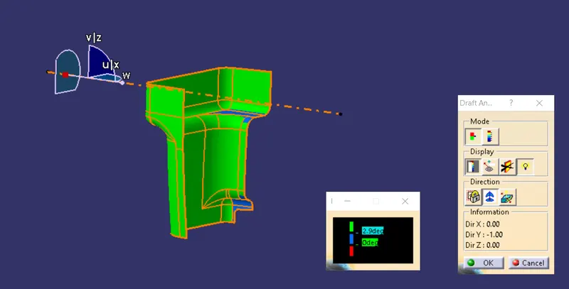
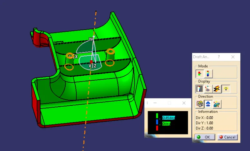
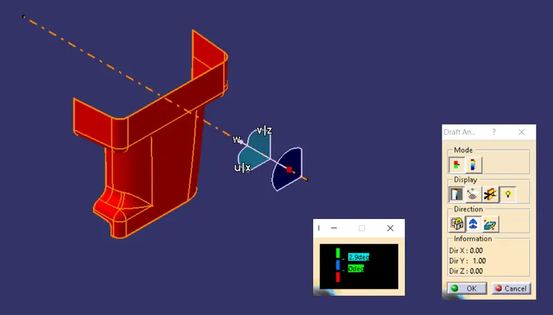
No parts can be ejected from the tool if it is having a straight 90degree profile from its base surface. A small draft angle is provide to component in order to get an easy removal from the tool. The draft analysis technique is used to analyze whether our part model created is manufacturable based on the draft condition applied. To perform draft analysis the view parameters are set to material mode.
To start the draft analysis, we will go to insert and click on the option called analysis. Select the Feature Draft Analysis, click on Quick Analysis option on mode. Under direction we will choose the icon with the symbol of compass on it. Place it o the tooling axis.
CLASS B SURFACE:
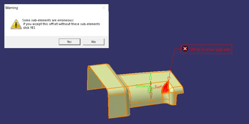
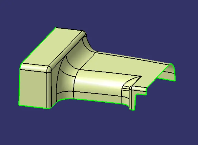
Class B surface is an offseted surface from the class A surface. B surface contains the features like ribs and screw boss. Offset the Class A surface for 2.5mm Downwards, Close all the gaps acquire.
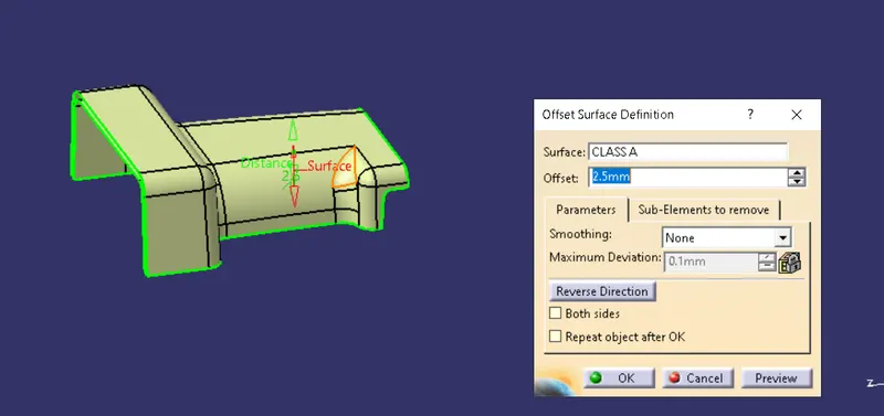
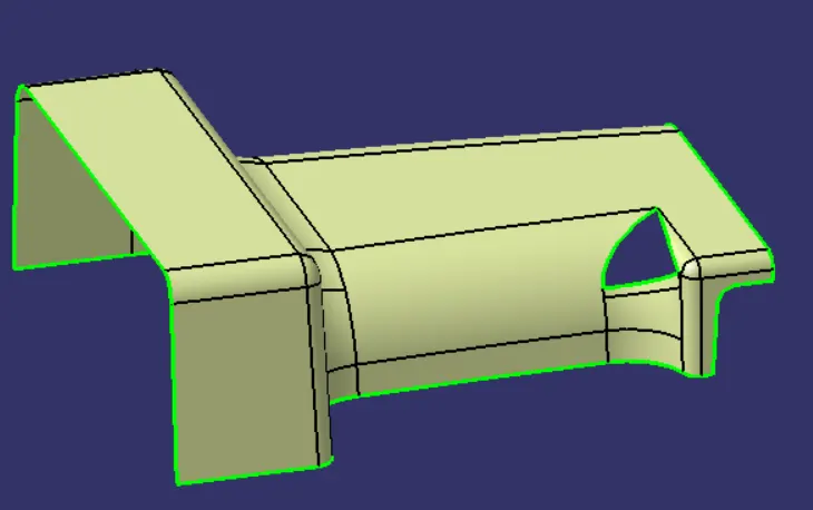
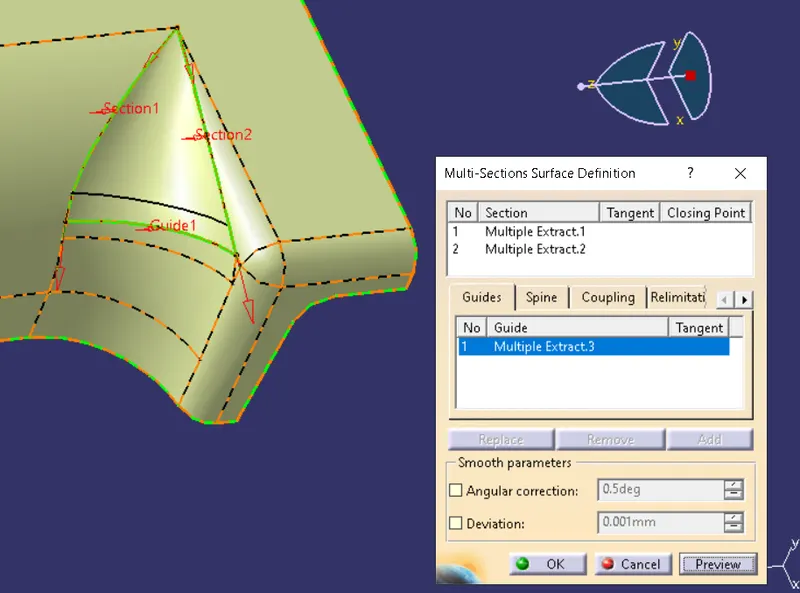
Using Multi-Sections surface close the gap, Extract the edges of the surface to get the sections and guide for the operation.
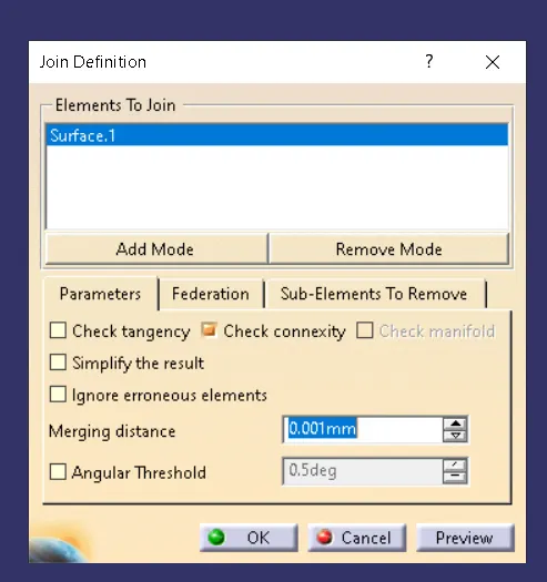
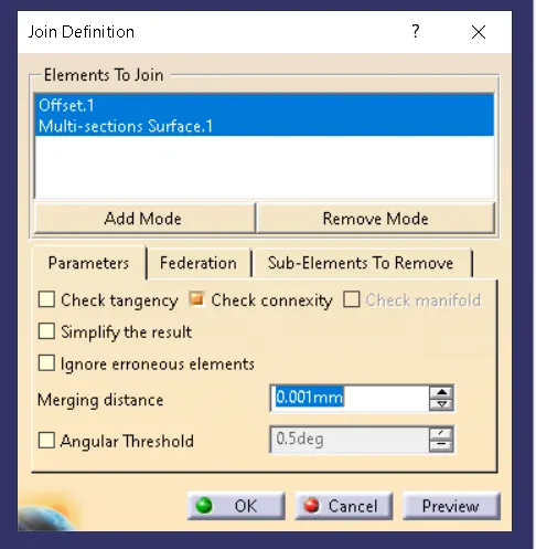
Join the Multi-sections surface with the offset surface to get the final Class B surface.
CLASS C SURFACE:
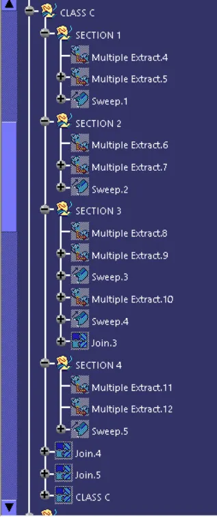
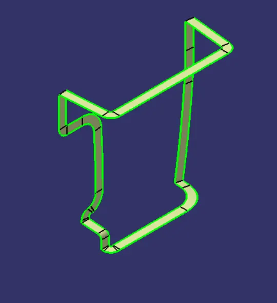
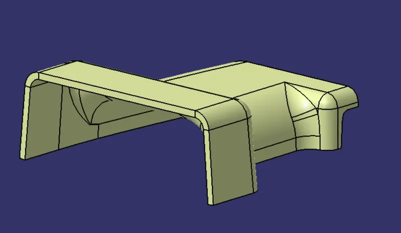
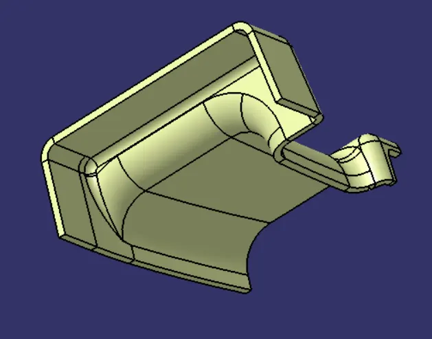
Class C surface Joins the Class A and B together to get the final plastic component. First join the Class A and C together, Then Trim the Class B surface with the joined Class A and C surface.
FINAL TRIM:
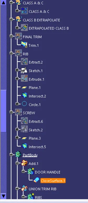
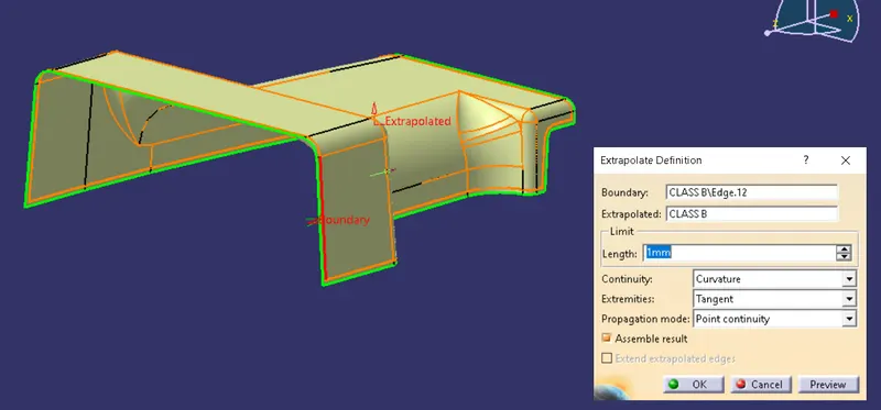
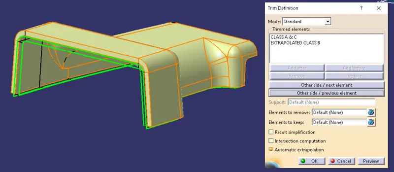
Extrapolate the Class B surface to intersect with the Class A & C surface. Trim them together to get the final component.
CLOSE SURFACE:
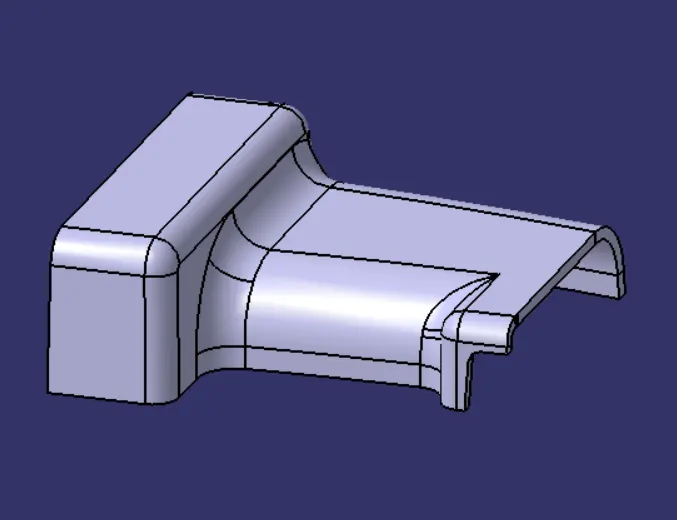
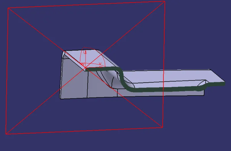
Open the part workbench convert the final trim surface into close surface.
RIB DESIGN:
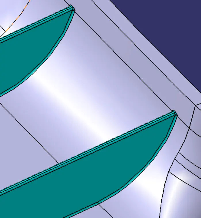
Create the sketch for the rib in the B side of the plastic component. Extract a surface on the B side, Create a positioned sketch on the surface.
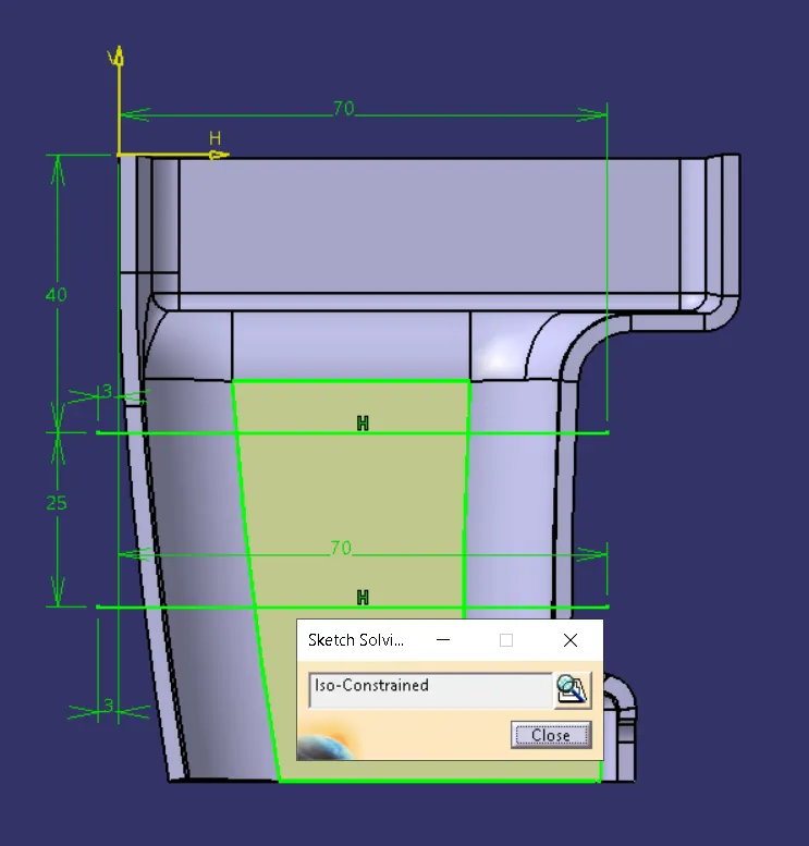
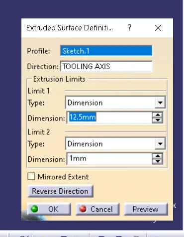
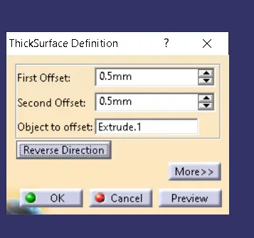
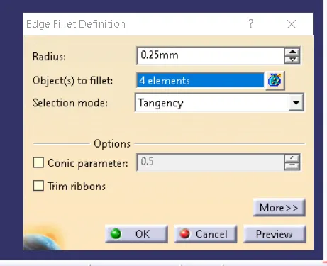
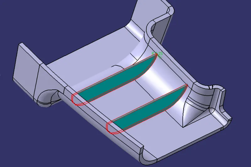
Extrude the sketch along the tooling axis, thicken the extruded surface and trim them together with the close surface. Fillet the surface .
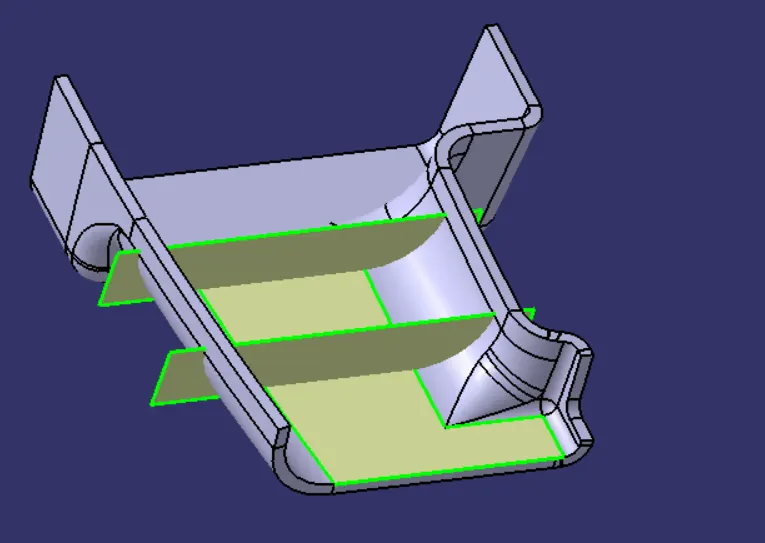
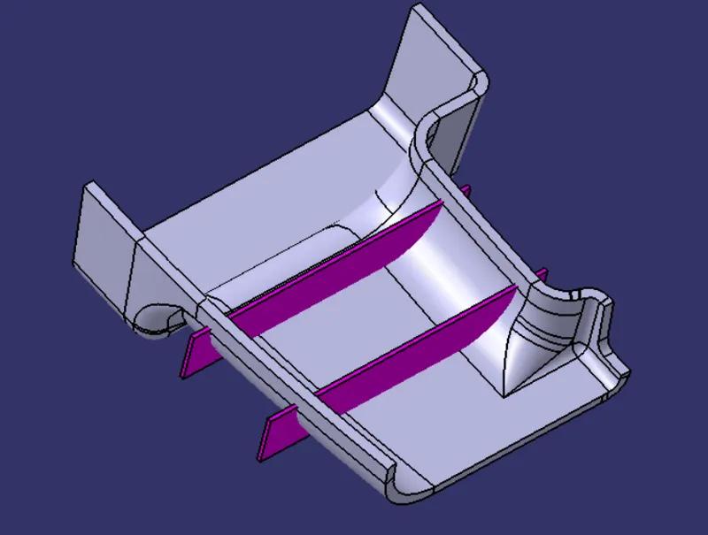
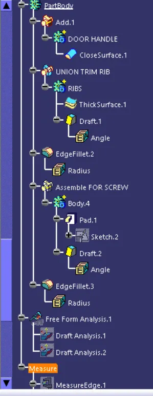
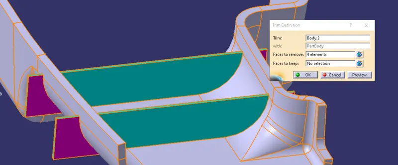
Using Union trim operation trim the extruded surface with the close surface, Select the surfaces which need to be removed from the surface.
DESIGN RULES FOR RIBS:
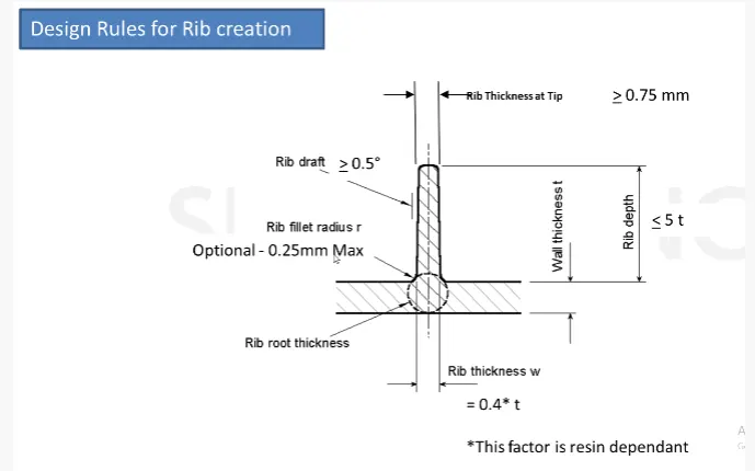
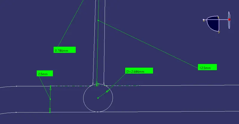
Height of the Rib should be Five times the Thickness of the base = 5*2.5
= 12.5mm.
Thickness of the Rib is 40 % * of base wall Thickness (2.5mm) = 40%*2.5
= 1mm.
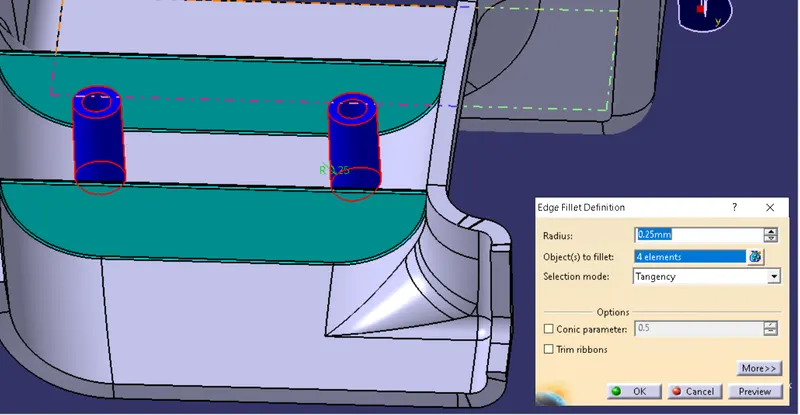
Rib Fillet Radius = 0.25mm.
Rib Draft = 0.5Degree.
Thickness at Tip = >0.75mm.
SCREW BOSS DESIGN:
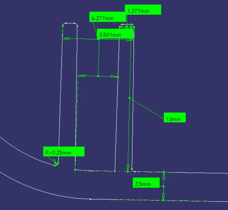
Create a sketch on the B side of the close surface, Create the screw diagram and pad the sketch .
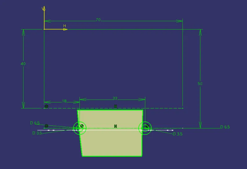
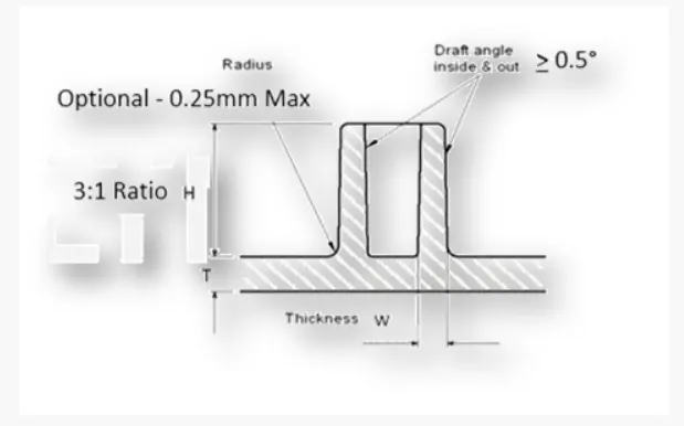
W = 0.6*T (Thickness of the base)
= 0.6*2.5
= 1.5
Whole Thickness of the screw is w*2 Added to the inner Thickness.
Outer Thickness = 1.5*2
= 3mm
whole Thickness = Inner Thickness + Outer Thickness
Lets consider Inner Thickness = 3.5mm
Thickness = 3.5 + 3
Outer Dia = 6.5 mm.
Height Of The screw = 3:1 or 2:1
= 2*6.5
Height of The Screw = 13mm.
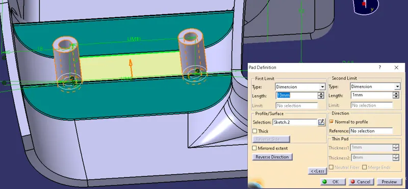
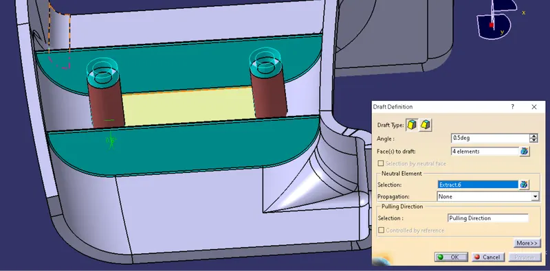
Apply Draft on the Both side of the Screw Boss.
FINAL DRAFT:
Perform Draft analysis on the final Product.
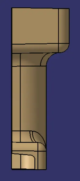
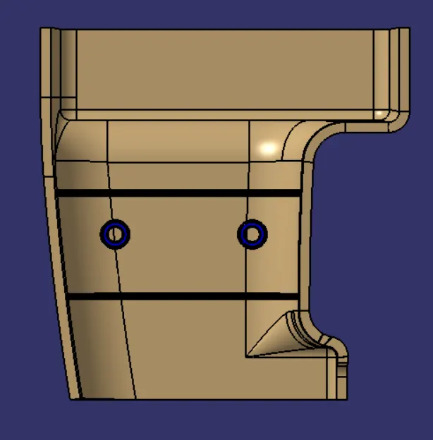
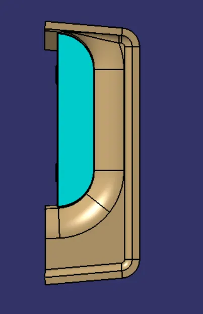
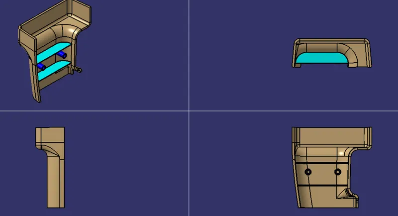
VIEWS:
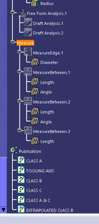
TREE STRUCTURE: