Photo Realistic Rendering
DESIGN AND ASSEMBLY OF AMERICAN CHOPPER
Objective:
To create a model of different parts of the chopper using soidworks.
To assemble the different parts modeled for the chopper.
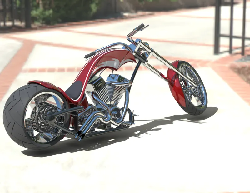
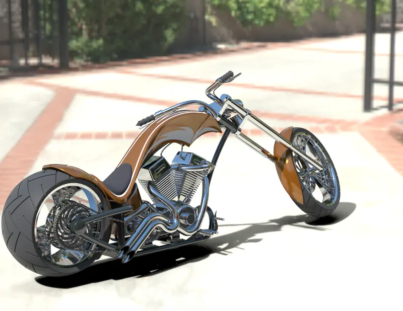
To create modelling and photo realistic rendering of American chopper by using solidworks.
Introduction:
This report contains a detailed explanation of design an American Chopper using Soidworks from part modelling to final rendering of the assembly.
Parts Modeled for Chopper:
The following parts of the Chopper are Modeled and assembled in Solidworks.
1. Transmission Belt
2. Kickstand
3. Front Fender
4. Rear Fender
5. Pedal
6. Chain
7. Oil Tank
8. Front Wheel
9. Rear Wheel
10. Front Fork
11. Chassis
12. Engine
13. Gas Tank
1. Transmission Belt:
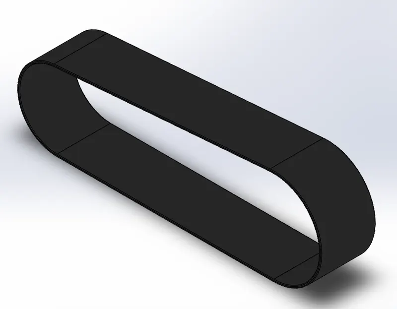
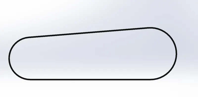
A belt is a loop of flexible material used to link two or more rotating shafts mechanically, most often parallel. Belts may be used as a source of motion, to transmit power efficiently or to track relative movement. The transmission belt is used to transfer power from the output shaft of the engine to the input shaft of the gear box.
Isometric view
Front view

Side view
Features Used:
Sketch
Boss Extrude
Fillet
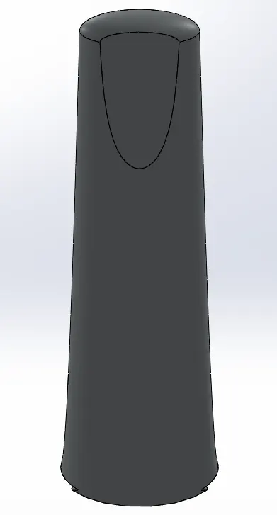
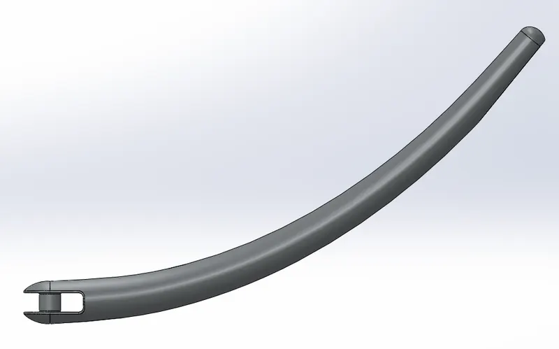
2. Kickstand:
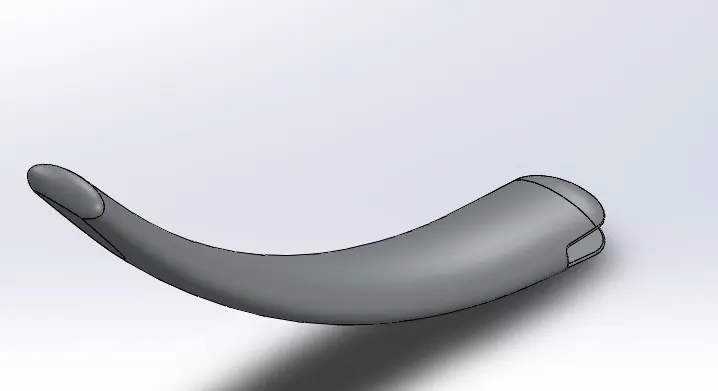
A Metal rod attached to a bicycle or motorcycle, lying horizontally when not in use, that may be kicked into a vertical position to support the vehicle when it is stationary.
Isometric view
Front view
Side view
Features Used:
Sketch
Boss Extrude
Loft
Dome
Cut Extrude
Split
Fillet
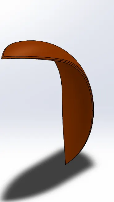
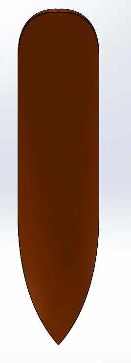
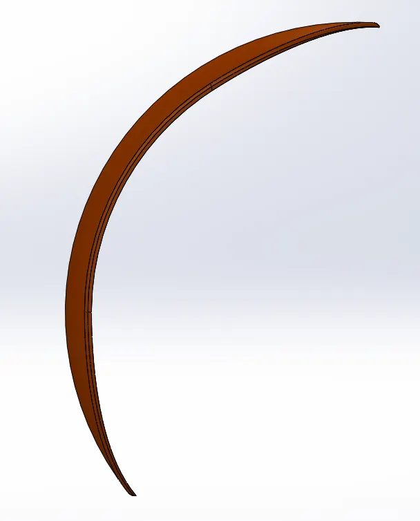
3. Front Fender:
A fender is essentially a covering for your bike tires that protects you from the rain. Riding with fenders will prevent the rain from splashing a streak of muddy water up your back, over your shoes and on your face. A front fender will help protect your feet and ankles from spray if you're riding in the rain or even through a puddle.
Isometric view
Front view
Side view
Features Used:
Sketch
Revolve
Split
Fillet
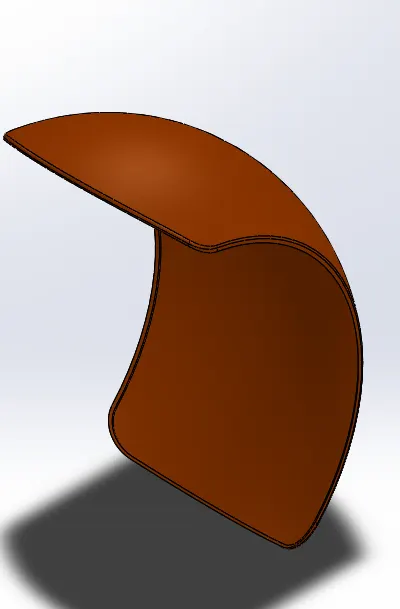
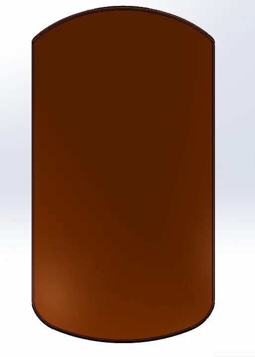
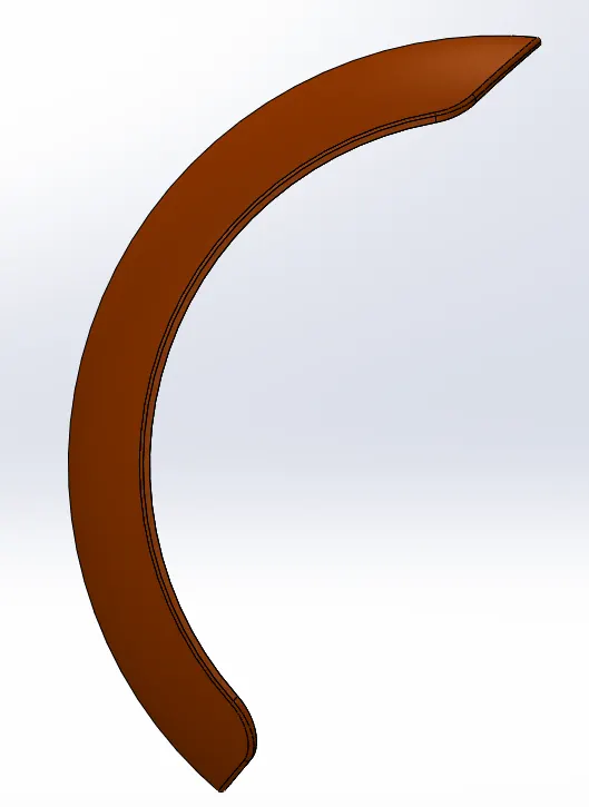
4. Rear Fender:
Fender is the American English term for the part of an automobile, motorcycle or other vehicle body that frames a wheel well. Its primary purpose is to prevent sand, mud, rocks, liquids, and other road spray from being thrown into the air by the rotating tire.
Isometric view
Front view
Side view
Features Used:
Sketch
Revolve
Split
Fillet
Shell
5. Pedal:
The External part mounted to the frame is the pedal. The pedal is used for the convenience of the rider. The rear brake is fixed in the right pedal and the gears are fixed in the left pedal.
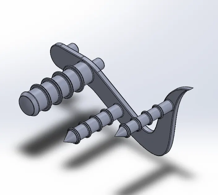
Isometric view
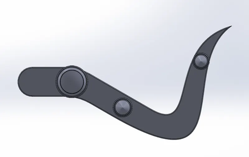
Front view
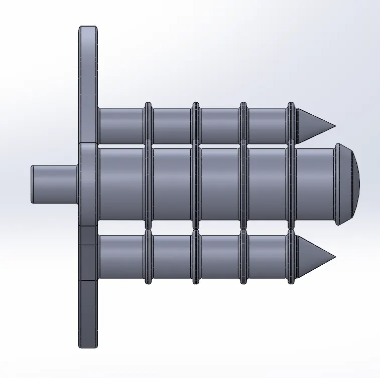
Side view
Features Used:
Sketch
Boss Extrude
Fillet
Revolve
Dome
Chamfer
Linear Pattern
6. Oil Tank:
The purpose of an oil tank is to store lube oil. The main job of the oil is to keep your engine lubricated, stopping metal to metal contact, and running as it should.
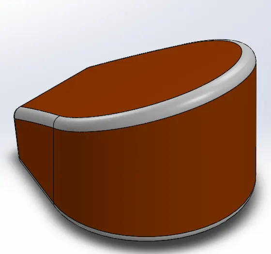
Isometric view
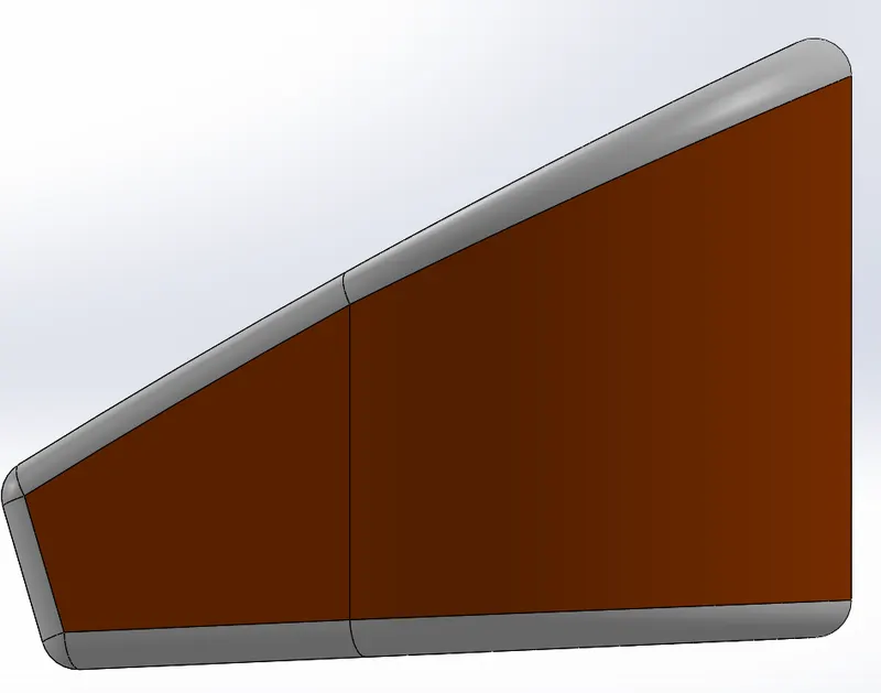
Front view
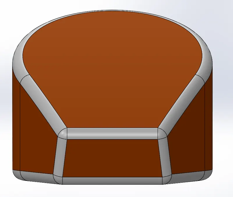
Side view
Features Used:
Sketch
Boss Extrude
Combine
Fillet
Shell
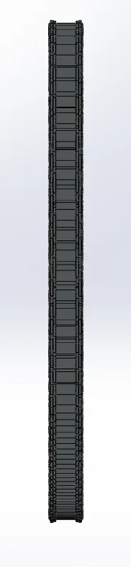
7. Chain:
Chain is the connection used to transmit power from the engine to the rear wheel. It passes over toothed member known as sprockets.
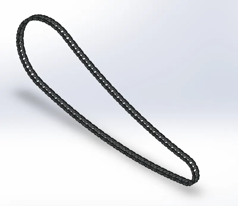
Isometric view
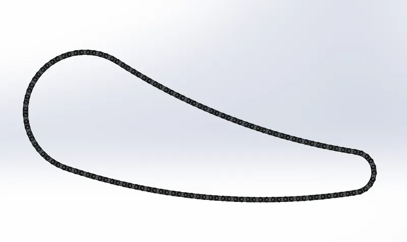
Front view
Side view
Features Used:
Sketch
Boss Extrude
Fillet
Curve Driven Pattern
Mirror
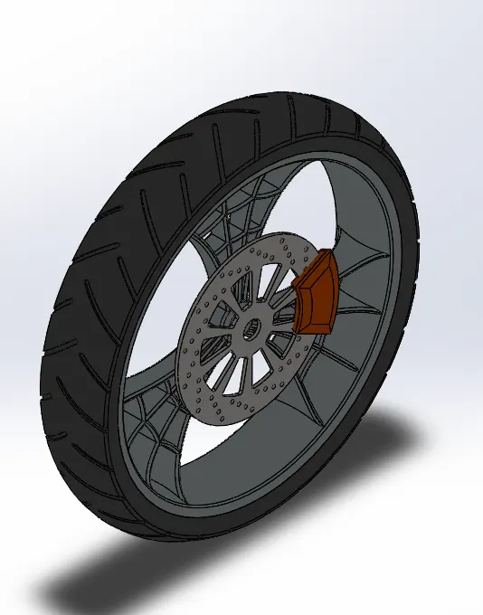
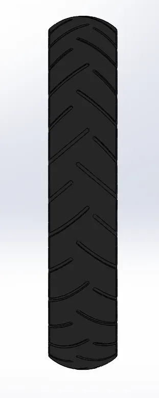
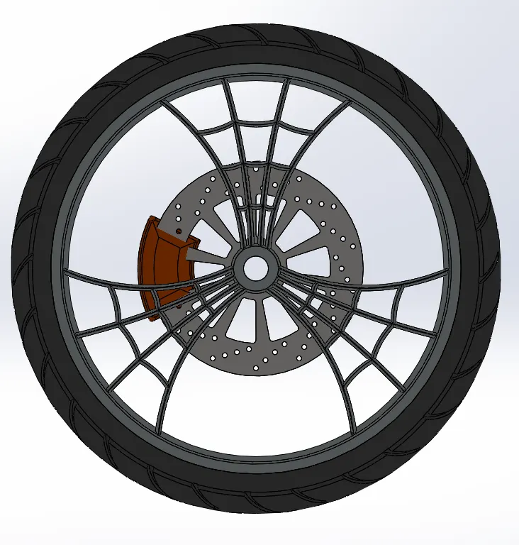
8. Front Wheel:
The main function of the front wheel is to take impact and steer the motorcycle. Having a taller, skinnier, front tire greatly helps with this functionality. The skinnier the tire, the more sensitive the motorcycle is to turning.
Isometric view
Front view
Side view
Features Used:
Sketch
Revolve
Boss Extrude
Cut Extrude
Cut Revolve
Cicular Pattern
Combine
Fillet
Chamfer
9. Rear Wheel:
A wheel is a circular block of a hard and durable material with a circular hole through an axle bearing around which the wheel rotates, where the middle has been drilled. The wider the back tire is, the more surface area there is that touches the road which means more traction.
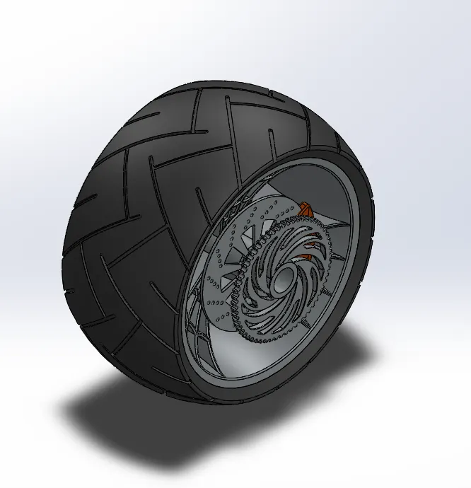
Isometic view
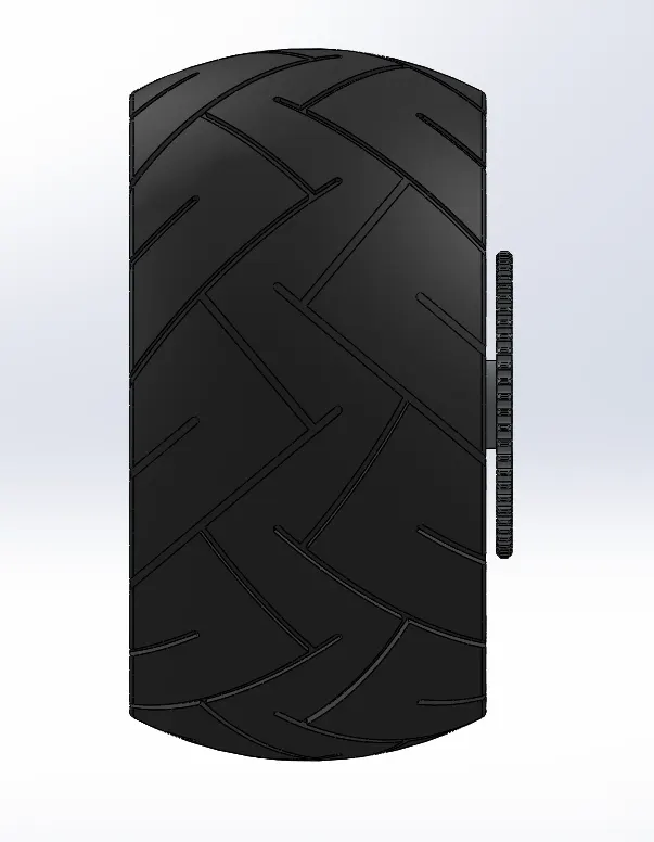
Front view
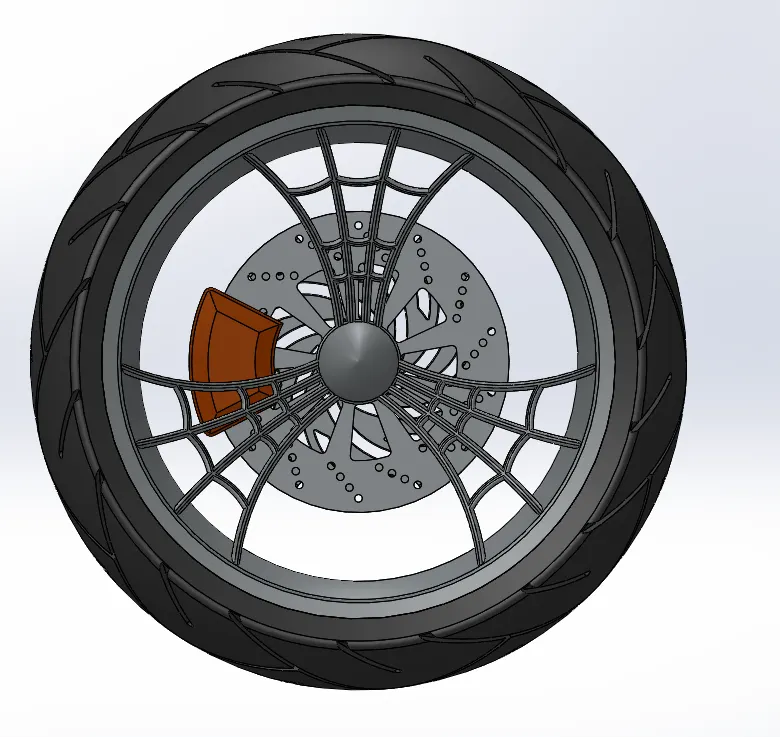
Side view
Features Used:
Sketch
Revolve
Boss Extrude
Cut Extrude
Circular Pattern
Combine
Cut Revolve
Fillet
Chamfer
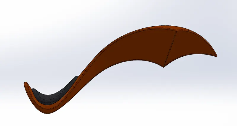
10. Gas Tank:
A gas tank is a safe container for flammable fluids. Though any storage tank for fuel may be so called, the term is typically applied to part of an engine system in which the fuel is stored and released into an engine.
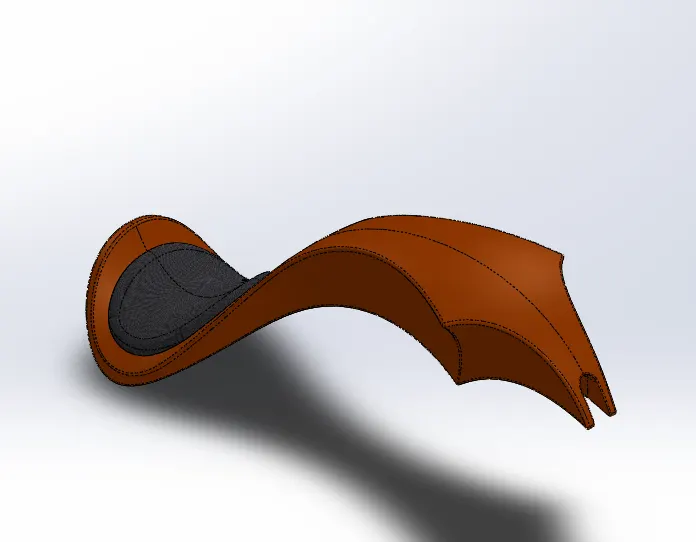
Isometic view
Front view
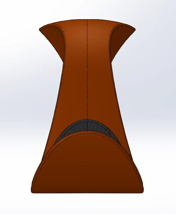
Side view
Features Used:
Sketch
Surface Sweep
Surface Trim
Curves
Surface Loft
Boundary Surface
Mirror
Surface Knit
Split Line
Surface Extrude
Fillet
Cut Sweep
Shell
11. Fork:
The fork is the suspension at the front of a motorcycle. In nearly every motorcycle available today, the front wheel is held on by an axle that's connected to the fork. It's called a fork because it has two prongs that go around each side of the wheel. They cause the front wheel to adapt to road imperfections while isolating the remainder of the motorcycle from the motion. To provide comfort to the rider, It removes the bums.
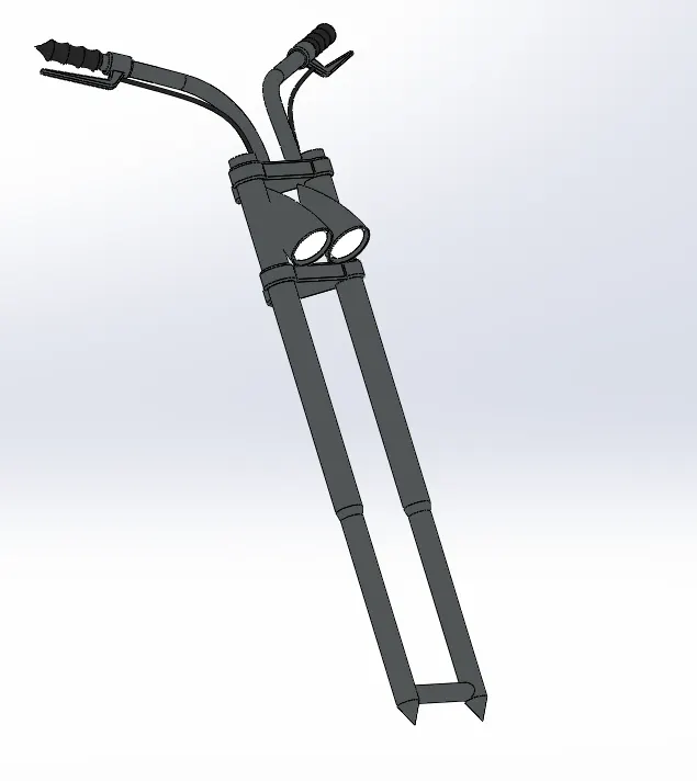
Isometic view

Front view

Side view
Features Used:
Sketch
Revolve
Boss Extrude
Fillet
Linear Pattern
Cut Extrude
Dome
Cut Revolve
Curves
Sweep
Mirror
Combine
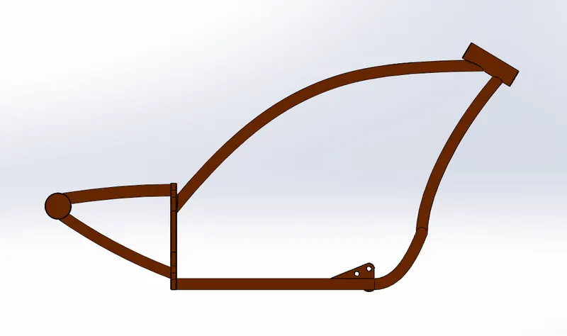
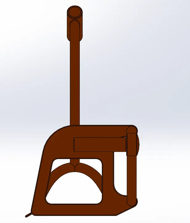
12. Chassis:
A chassis is a motorcycle's core structure. It supports the engine, provides a location for the steering and rear supensions, and suports the rider and any passenger or luggage. Also attached to the frame are the fuel tank and engine. All of the motorcycle's parts, such as the suspension, wheels, fuel tanks, seats, are related to this simple structure that gives a motorcycle its power and capacity to handle well.
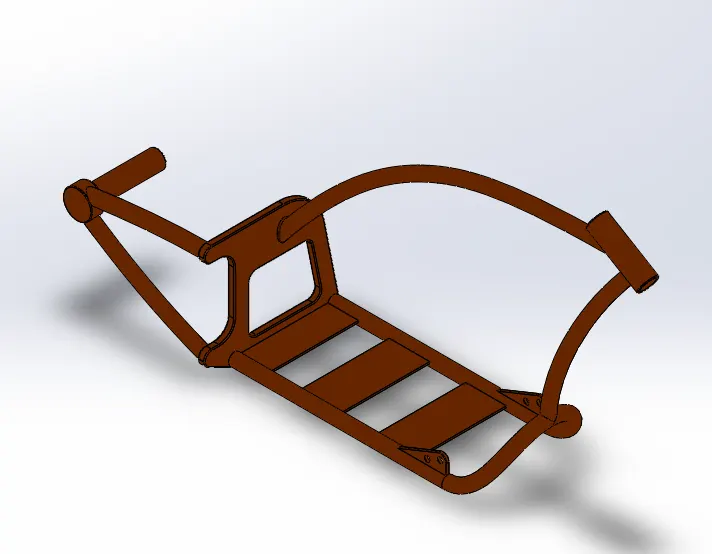
Isometric view
Front view
Side view
Features Used:
Sketch
Curves
Sweep
Mirror
Boss EXtrude
Cut Extrude
Chamfer
Fillet
Dome
Split
Combine
Revolve
13. Engine:
A motorcycle engine is an engine that powers a motorcycle. An engine is a system that is designed to transform heat into mechanical energy. The rider changes gears on most motorcycles using a foot pedal and manual clutch. Most engines have a gearbox with up to six or even seven ratios.
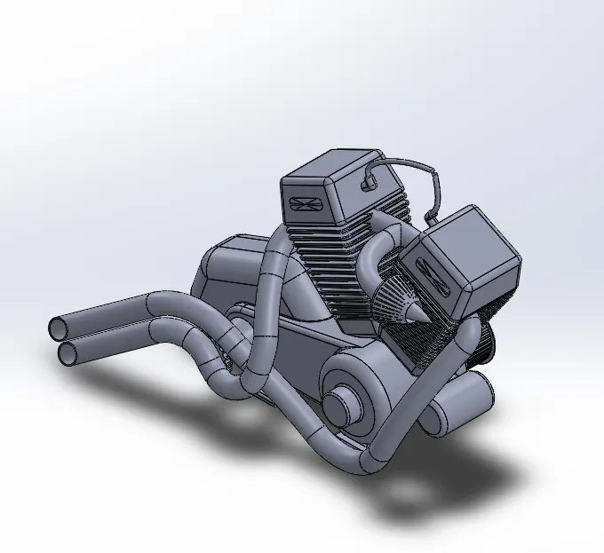
Isometric view
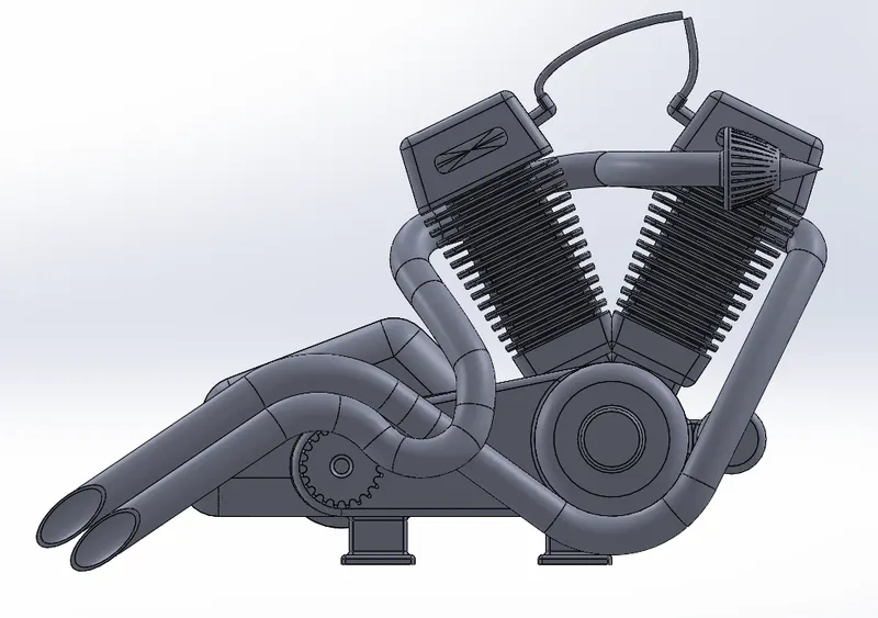
Front view
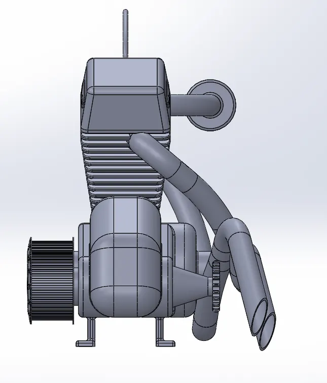
Side view
Features Used:
Sketch
Boss Extrude
Fillet
Revolve
Dome
Circular pattern
Cut Extrude
Chamfer
Linear Pattern
Mirror
Split
Sweep
Combine
Composite Curve
Assembly:
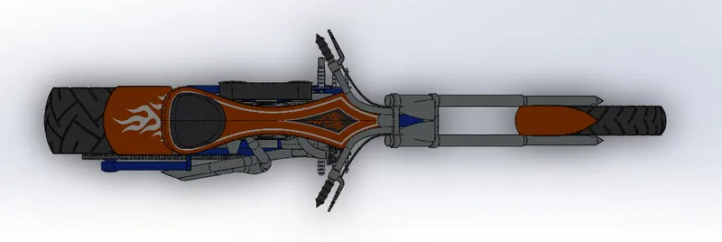
In the assembly part, all indvidual parts inserted into assembly tools of solidworks. Fix the Chassis in the work base. At first we need to open the assembly part and add an existing parts or subassembly to the assemly. Once the chassis is fixed we need to fix all other parts with the chassis using mates(position two components relative to one another).
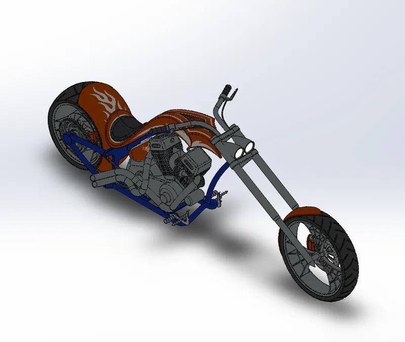
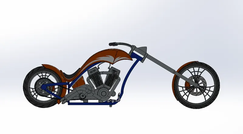
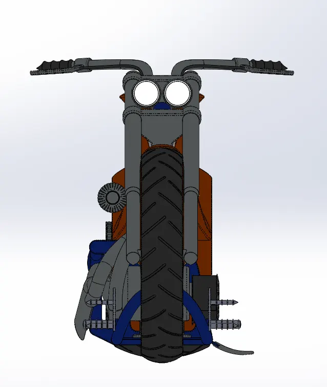
Mates Used:
Coincident
Concentric
Tangent
Parallel
Distance
Advanced Mate
Limit Angle
Rendering:
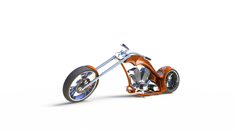
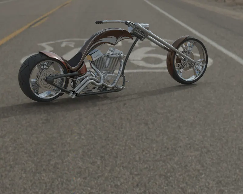
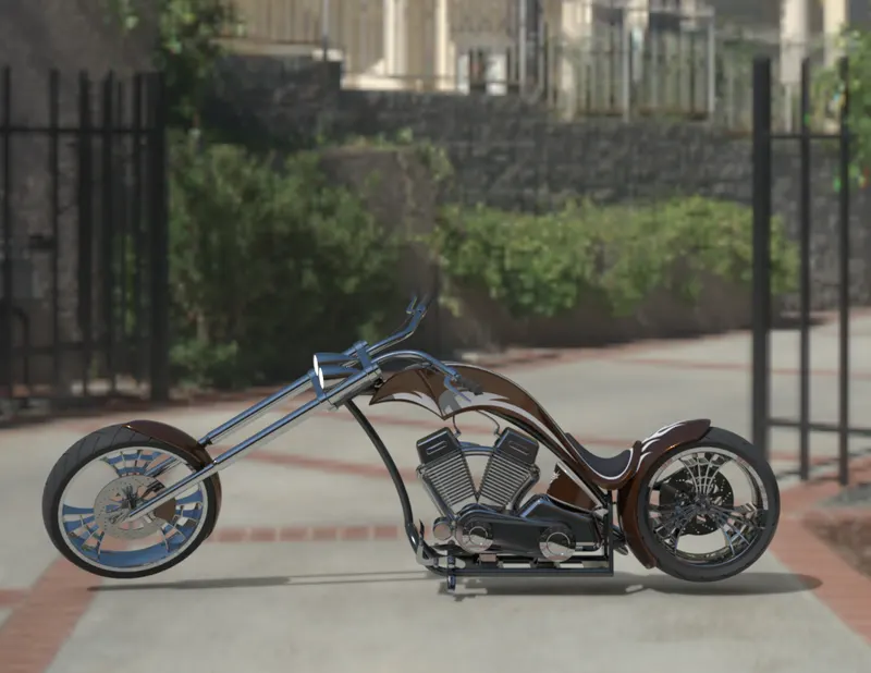
Rendering is the method of making with the reality accurate representations of the photorealistic model. In solidworks, rendering has been accomplished in two respects. The two manners are as follows,
1. Photoview 360
2. Solidworks Visualize

Features Description:
Sketch:
To draw a 2D diagram of the part we are going to create, create a new sketch, or edit an existing sketch.
Boss Extrude:
Extrudes a sketch or selected sketch contours in one or two dirctions to create a solid feature.
Revolve:
Revolves a sketch or selected sketch contours around an axis to create a solid feature.
Swept:
Sweeps a closed profile along an open or closed path to create a solid feature.
Trim Entities:
Trims or extends a sketch entity to be coincident to another, or deletes a sketch entity.
Convert Entities:
Converts selected model edges or sketch entities into sketch segments.
Offset Entities:
Adds sketch entities by offsetting faces, edges, curves, or sketch entities a specified distance.
Mirror Entities:
Mirrors selected entities about a centerline or planar reference.
Linear Sketch Pattern:
Adds a linear pattern of sketch entities.
Cicular Sketch Pattern:
Adds a circular pattern of sketch entities.
Fillet:
Creates a rounded internal or external face along one or more edges in solid or surface feature.
Shell:
Removes material from a solid body to create a thin-walled feature.
Mirror:
Mirrors features, faces, and bodies about a face or a plane.
Cut Extrude:
Cuts a solid model by extruding a sketched profile in one or two directions.
Revolved Cut:
Cuts a solid model by revolving a sketched profile around an axis.
Knit Surface:
Combines two or more adjacent, non-intersecting surfaes together.
Dome:
Adds one or more domes to selected planar or non-planar faces.
Conclusion:
The components of the chopper ae sketched and modelled in solidworks.
The components are placed into the setting of the assembly and assembled by applying the mates chopper.
Using photoview 360 & Solidworks visualize, the realistic image was rendered.