Week 8 - Challenge 2 - Switch Bezel Design
SWITCH BEZEL DESIGN
INTRODUCTON:
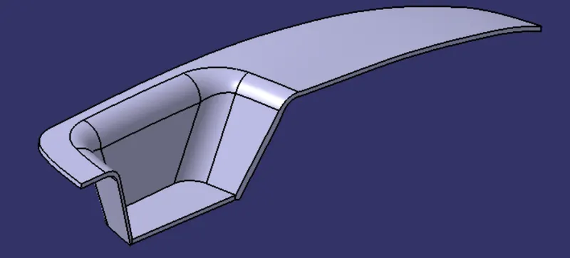
To create a Switch Bezel Plastic Component through a given Class A surface and perform Draft Analysis on the final plastic component.
OBJECTIVES:
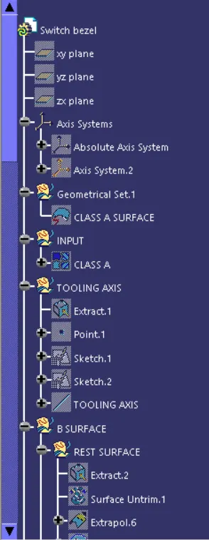
Create the Tooling Axis
Create the Class B and C surface
Create the Close Surface
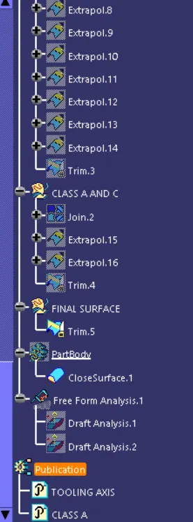
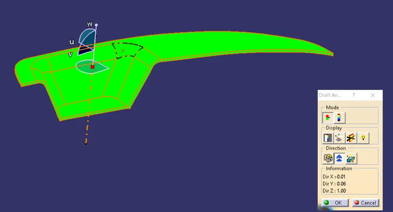
Perform Draft Analysis
SPECIFICATIONS:
Switch Bezel Thickness = 2.5mm
Minimum Draft Angle = 3 Degree
CLASS A SURFACE:
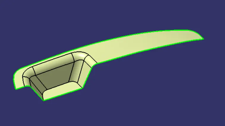
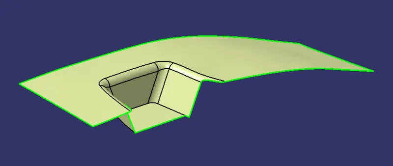
The first thing to do is to check for the connectivity of the surface this is to ensure that there are no gaps between the surfaces, if gaps are present then it should be resolved. This can be done by creating boundaries, if their are gaps present they are represented by green lines.
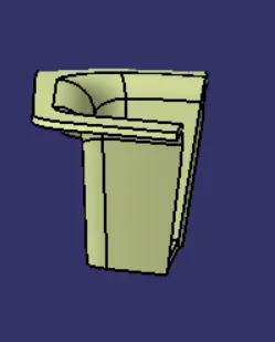
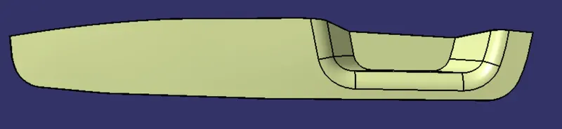
Class A surfaces are primarily used in the automotive environment and refer to those surfaces which are visible in a product. In automotive design, a class A surfcae is any of a set of freedom surfaces of high efficiency and quality. The class A surface provided is SWITCH BEZEL, from the given Class A surface i created the class B and C surface.
TOOLING AXIS:
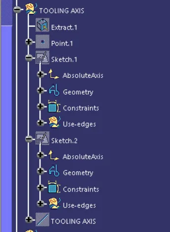
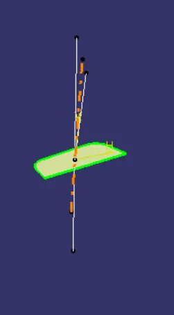
A dummy axis is created for reference, This is a normal line which i construct by analysing the best possible direction for the draft. Taking the dummy axis as as reference, intersect the class A surface along the different axis, check for possible places where the part might face difficulties while ejecting the componenet from the mold. using the intersection lines will be created along the inclined walls, these lines are used for creation of tooling axis by Bisecting Method.
DRAFT ANALYSIS:
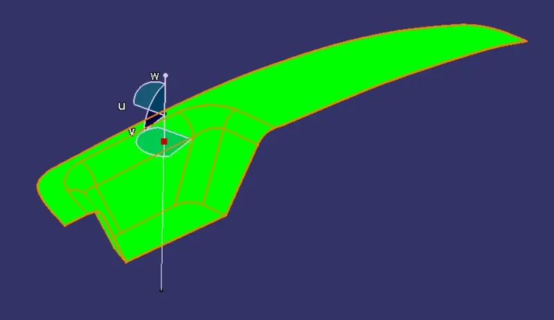
The draft analysis technique is used to analyze whether our part model created is manufacturable based on the draft condition applied.

CLASS B SURFACE:
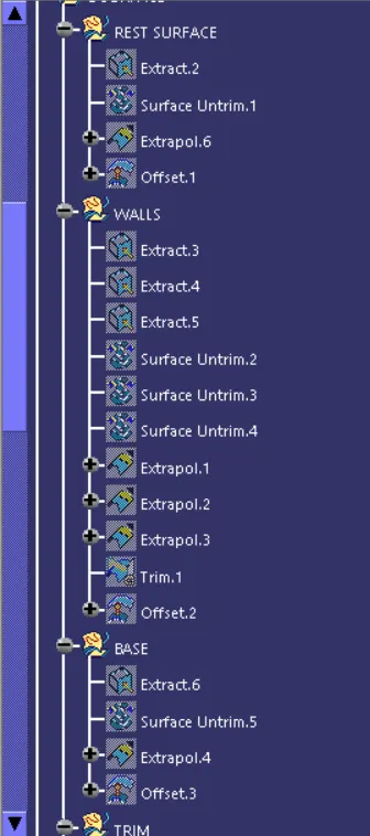
Extract the parts which is need to be offset to create the class B surface. I extracted the side walls, Base, Top of the switch bezel and untrim them and then i extrapolate the surfaces. Trim the sufaces together and then offset them to create the Class B surface.
CLASS C SURFACE:
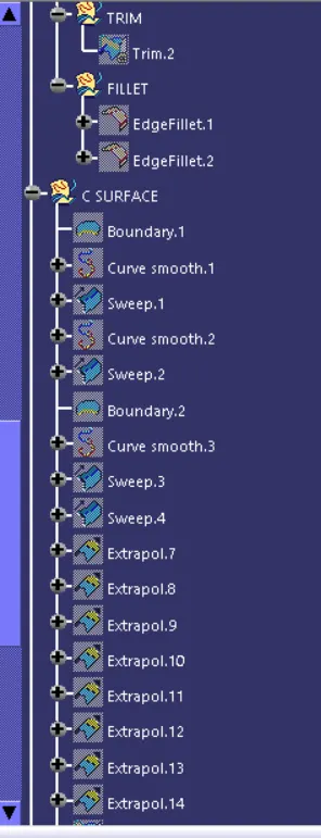
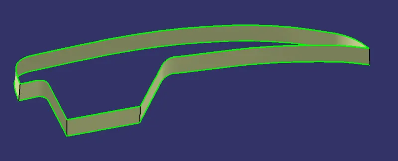
The class C surface is created by doing a sweep along the bounary of the class A surface. Extract the boundaries seperately and extrapolate all the edges, Trim all the surfaces together. Join the Class C with the Class A surfcae and then trim them with Class B to create the final Plastic Component.
CLASS A AND C SURFACE:
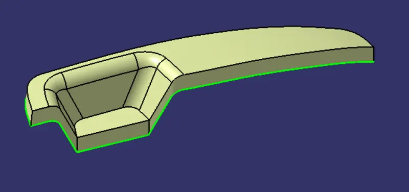
Join the class A and C together.
FINAL TRIM:
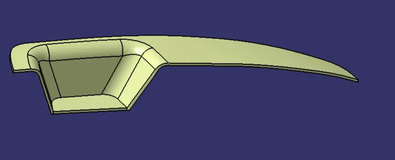
Trim the joined surface with the class B surface to get the final plastic component.
OPERATIONS USED:
Axis System
Join
Extract
Positioned Sketch
Surface Untrim
Extrapolate
Offset
Trim
Fillet
Boundary
Smooth Curve
Sweep
Close Surface
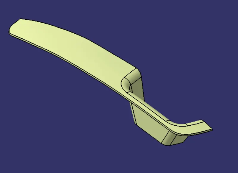
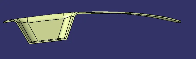
VIEWS:
TREE STRUCTURE: