Radar Mast & Final Assembly of Yacht
DESIGN AND ASSEMBLY OF PREDATOR YACHT
Objective:
To design the different parts of the predator yacht using solidworks.
To assemble the different parts created for the yacht.
To create a photorealistic render for the final model using solidworks.
Introduction:
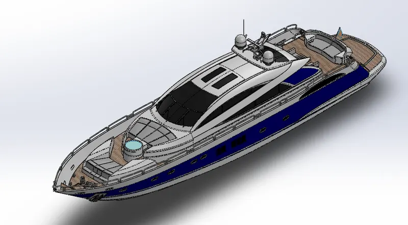
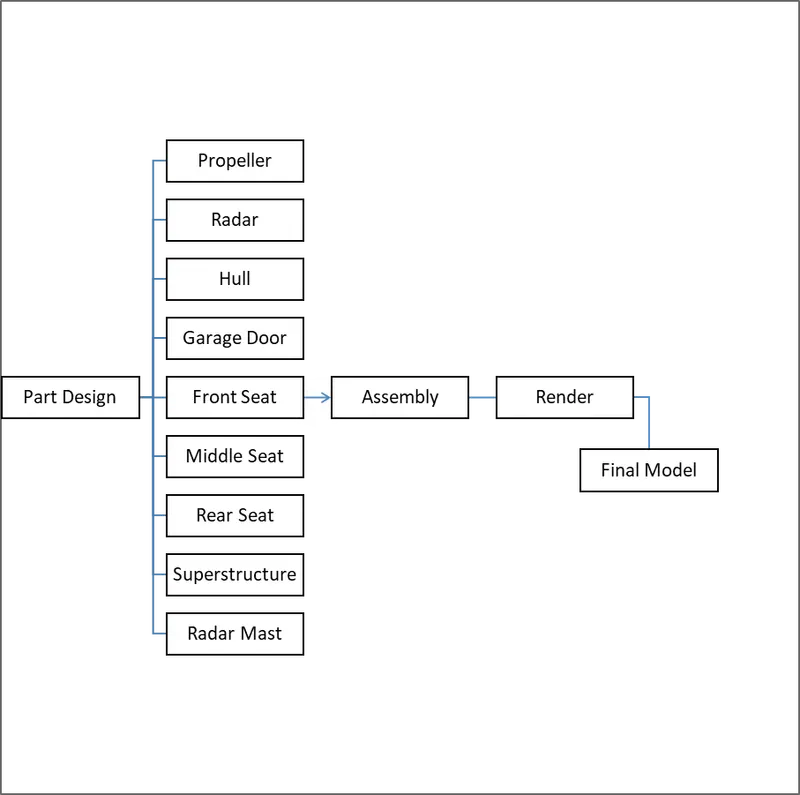
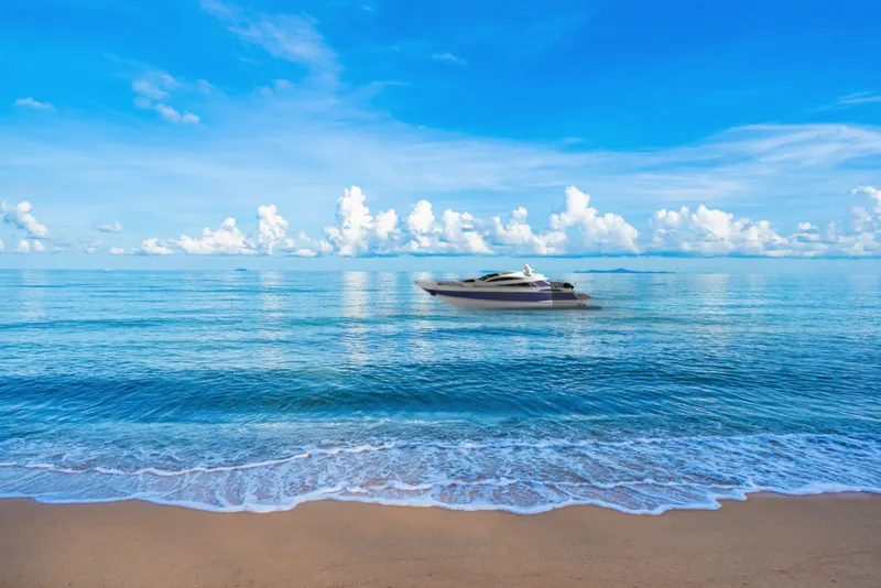
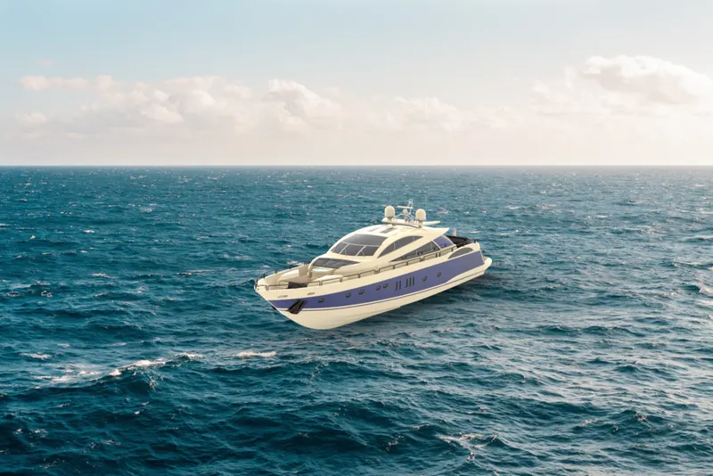
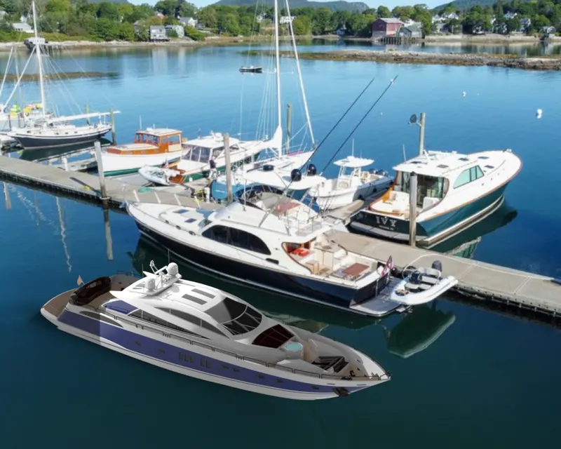
This report contains a detailed explanation of designing an predator yacht using solidworks from part modelling to final render of the assembly.In this project the predator yacht was taken as model, to understand the 3D modelling methods of solid modelling and surface modelling.Every part of the yacht was designed and assembled using solidworks.Then the parts were assembled by adding proper mate to create a photorealistic rendered image of the yacht.
Parts modelled for yacht:
1. Propeller
2. Radar
3. Hull
4. Garage door
5. Front seat
6. Middle seat
7. Rear seat
8. Superstructure
9. Radarmast
1.Propeller:
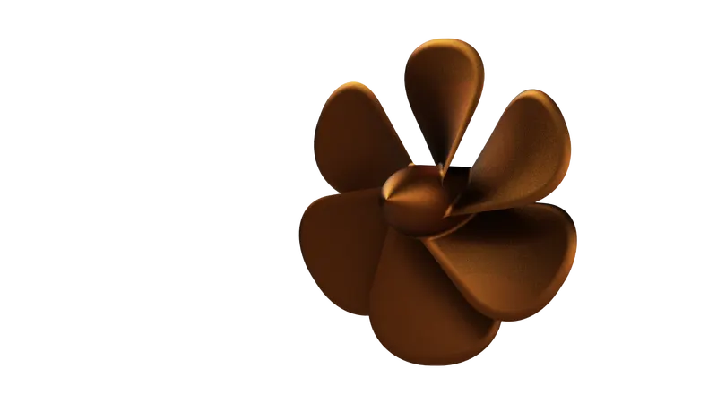
A propeller is a device with a rotating hub and radiating blades that are set to a pitch to form a helical spiral which,when rotated,exerts linear thrust upon a working fluid such as water or air.

Render Image:
Features Used:
Sketch
Plane
Revolve
Loft
Fillet
Cut Extrude
Circular Pattern
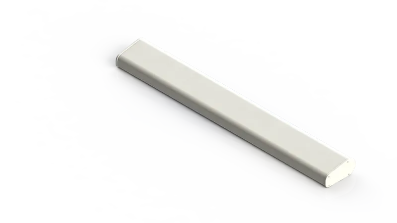
2.Radar:
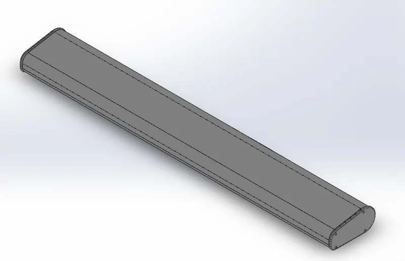
A radar is an instrument that can detect surrounding objects using radio waves.Thus,in the maritime world,objects such as ships,buoys or birds can be detected by radars.
Render Image:
Features Used:
Sketch
Boss Extrude
Cut Extrude
Fillet
Sketch Pattern
Mirror
Split Line
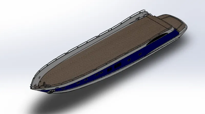
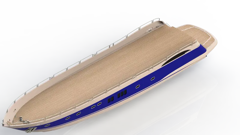
3.Hull:
A hull is the body of the yacht.That maybe open at the top or it maybe coverd with a deck.The hull contains the engine and some room for storage,on top of the hull the structure,seats and cabins for the yacht is present.The line where the hull meets the water surface is called the waterline.
Render Image:
Features Used:
Sketch, 3D Sketch, Plane
Surface Loft, Surface Trim, Surface Extrude
Surface Knit, Surface Fill, Deck Surface
Curve, Fillet, Shell, Chamfer
Boss Extrude, Cut Extrude
Sweep, Revolve, Dome, Split
Helix/spiral, Linear Pattern,
Mirror, Split Line
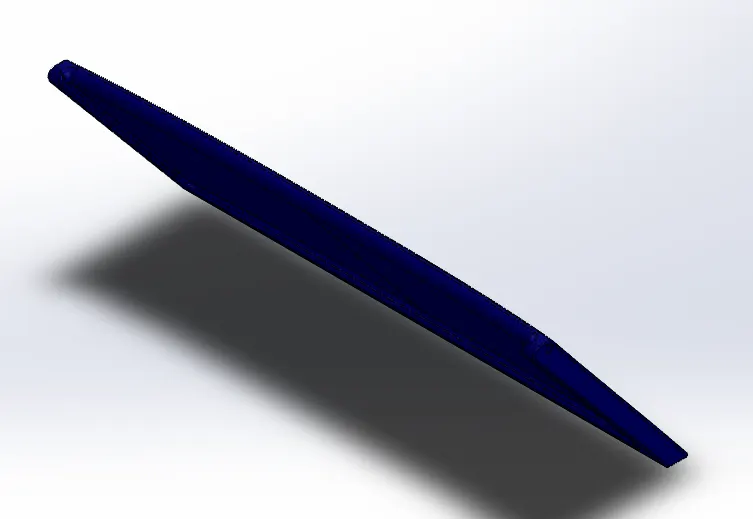
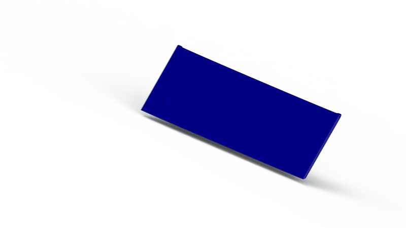
4.Garage Door:
The garage door generaly used to accommodate automobiles and other vehicles.The door works either manualy or electricaly.
Render Image:
Features Used:
Sketch
Shell
Cut Extrude
Fillet
Mirror
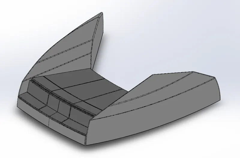
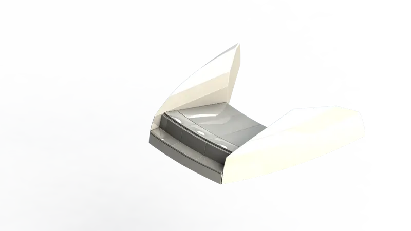
5.Front Seat:
The purpose of the seat is to make people comfortable during their whole travel,the front seat is taken place in front portion of the yacht.
Render Image:
Features Used:
sketch, Revolve, Chamfer
Surface Extrude, Surface Sweep
Surface Trim, Surface fill, Fillet
Surface Loft, Surface Knit
Mirror, Dome, Cut Extrude
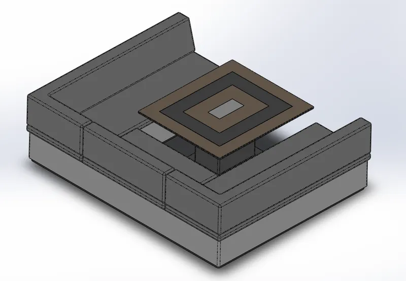
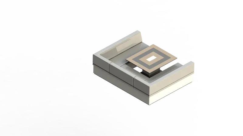
6.Middle Seat:
The middle seat is took place in the middle part of the yacht at back side of the superstructure.
Render Image:
Features Used:
Sketch
Boss Extrude
Cut Extrude
Fillet
Chamfer
Mirror
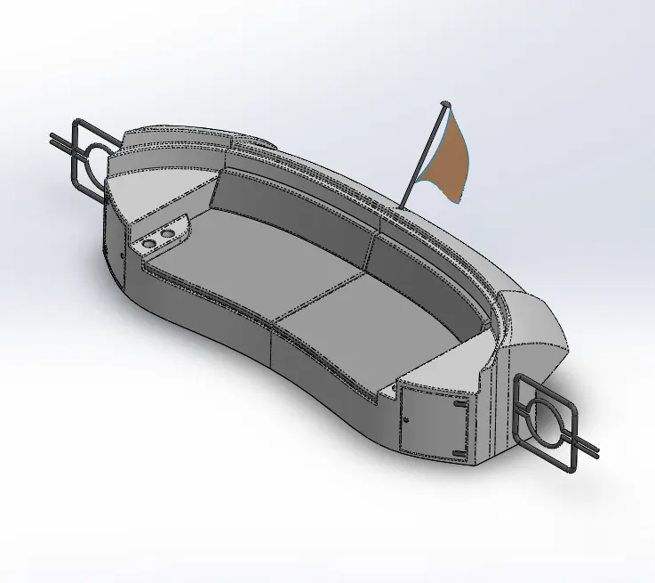
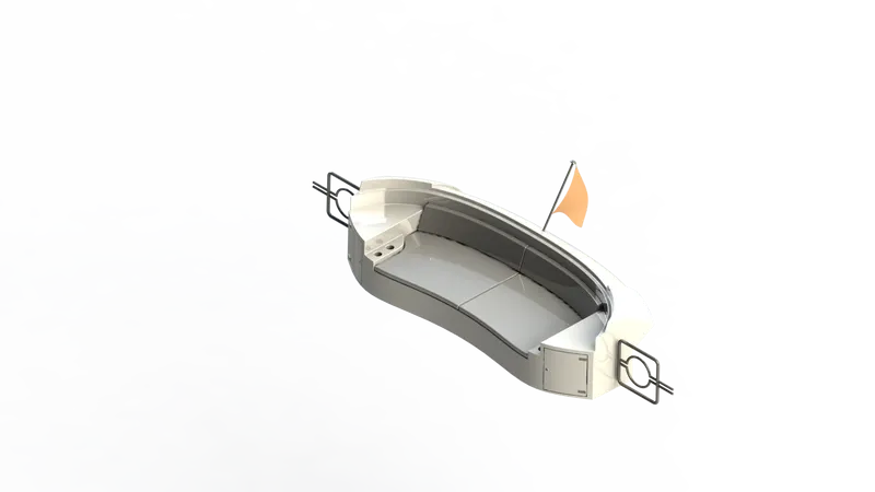
7.Rear Seat:
The rear seat is on the back side of the yacht.It took place on top of the hull at the end of deck surface.
Render Image:
Features Used:
Sketch, 3D Sketch, Revolve
Surface Sweep, Surface Offset
Surface Trim, Surface Knit
Surface Extend, Surface Extrude
Surface Loft, Ruled Surface
Boss Extrude, Cut Extrude
Fillet, Chamfer, Sweep, Mirror
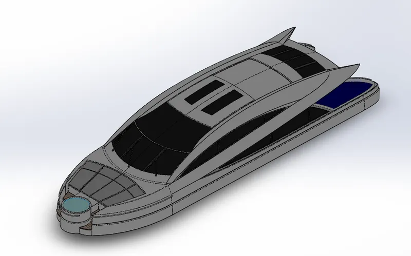
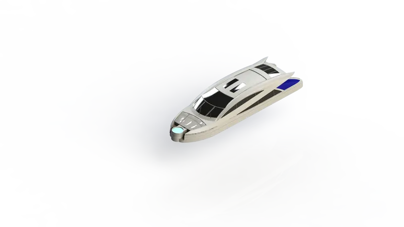
8.Superstructure:
A superstructure is an extended construction of any platform that rises above the rest of the platform in a distinct manner.Thus,superstructure means to add construction to an already existing structure.In ships,this is the name given to the part of the ship that emerges from the deck.
Render Image:
Features Used:
Sketch, 3D Sketch, Curve
Fillet, Thicken, Dome, Sweep
Extrude Thin, Split Line, Chamfer
Surface Extrude, Surface Sweep
Surface Offset, Surface Knit
Surface Trim, Surface Loft
Surface Fill, Surface Extend
Ruled Surface, Delete Face
Mirror, Boss Extrude, Cut Extrude
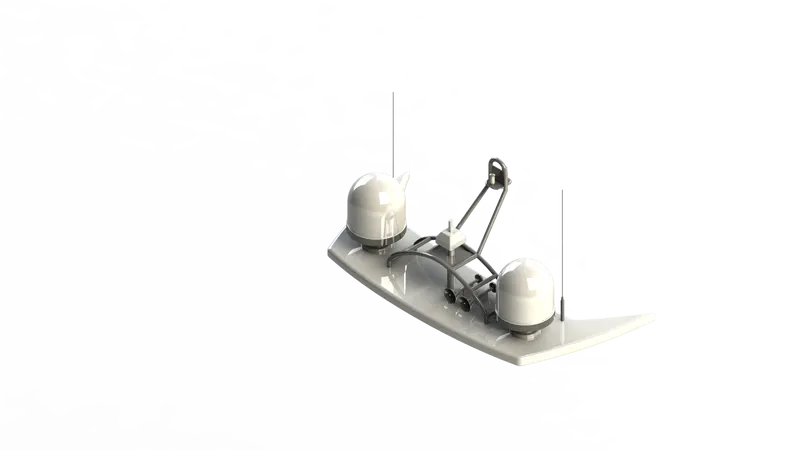
9.Radarmast:
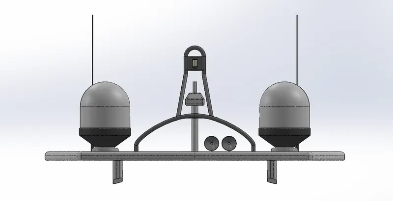
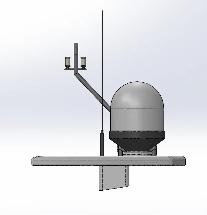
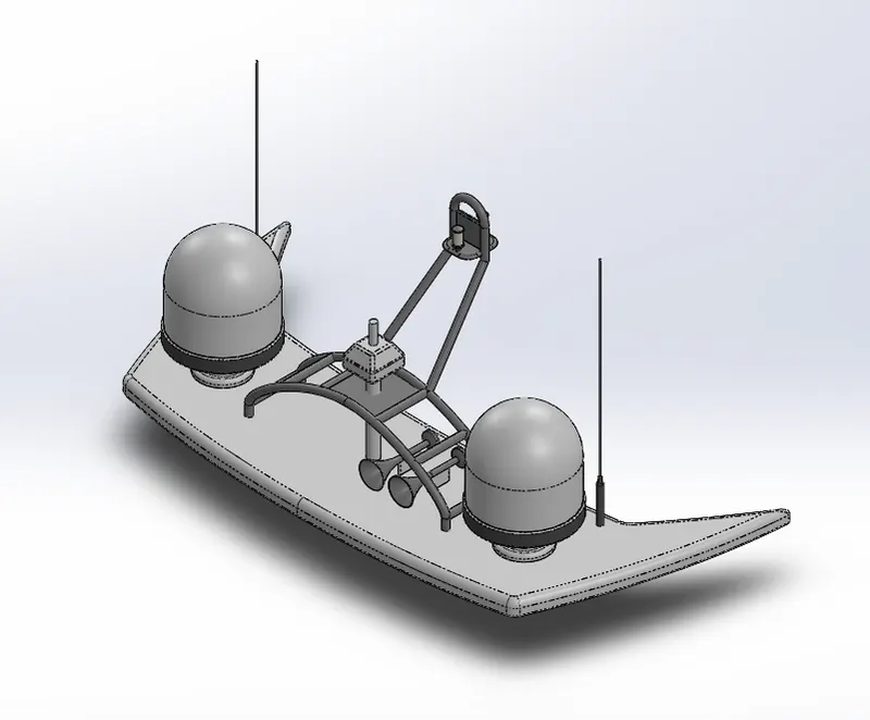
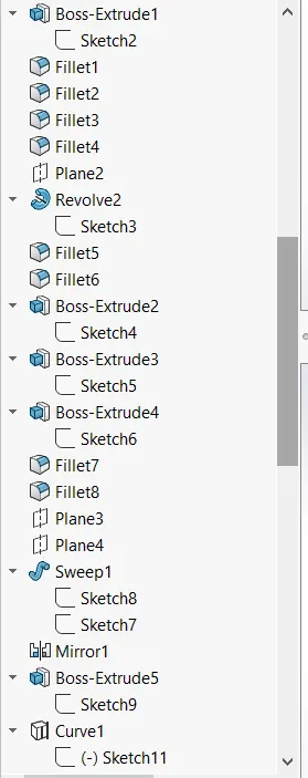
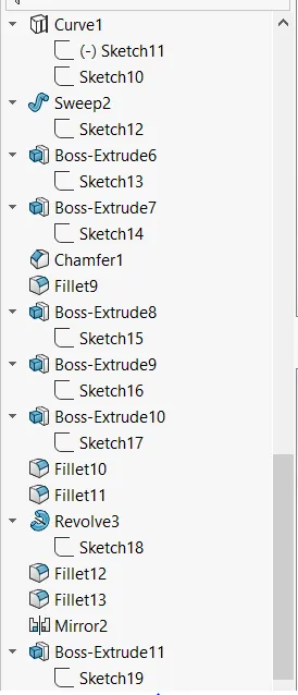
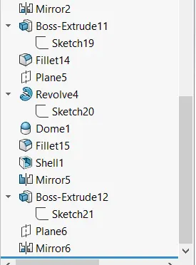
A mast is a vertical ship structure mounted on top of bridge and forward of the forecastle towards the ships bow.It accounts for the support platform for the ships derrick and hold necessary equipments such as radars,navigation light and ships horn in case of foremast.They are made of high tensile steel with added rigidity based on the size of derricks it holds. Other than that a ships main mast is also used to hoist ships flag.
Render Image:
Features Used:
Sketch
Boss Extrude
Fillet
Revolve
Sweep
Mirror
Curve
Chamfer
Dome
Shell
Features Description:
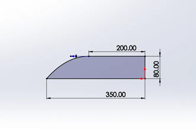
Sketch:
The sketch is the basis for a 3D model.You can create a sketch on any of the default planes (Front plane,Top plane,and Right plane), or a created plane.You can start by sketching:Sketch entity tools(line,circle,and so on).
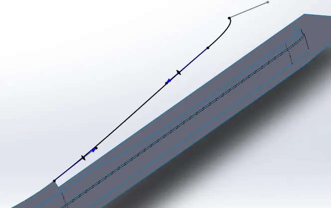
3D Sketch:
You can create 3D Sketch entities on a working plane, or at any arbitrary point in a 3D space.Just like its counterpart, the 3D sketch tool creates geometry by using points,lines,splines and any other sketchable shape to define a profie.Whats different about 3D sketching is that instead of drawing on a single plane, 3D sketching can exist on multiple planes simultaneously.
Boss Extrude:
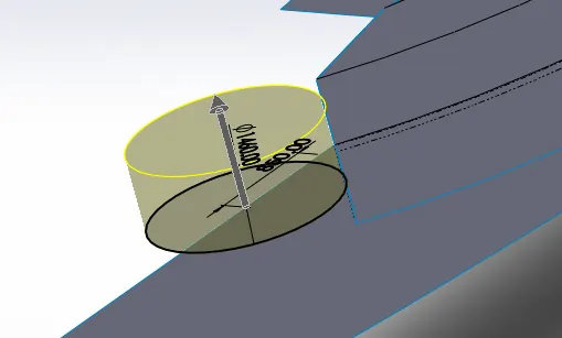
Extrudes a sketch or selected sketch countours in one or two directions to create a solid feature.
Cut Extrude:
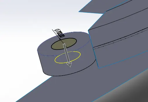
Extruded cut feature removes material from the part.Cuts a solid model by extruding a sketched profile in one or two diections.
Revolve:
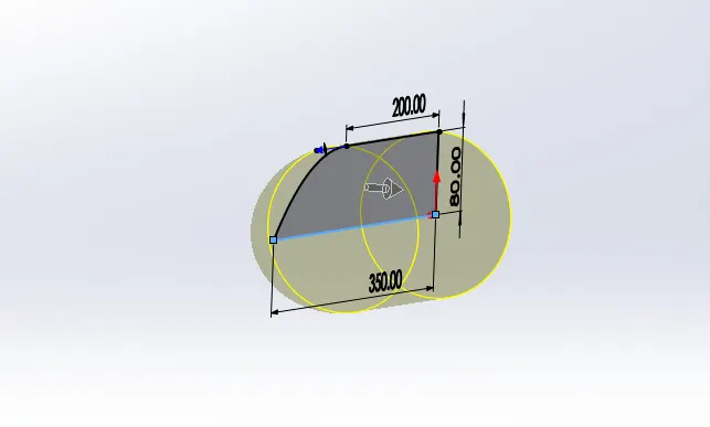
The revolve feature creates geometry from a sketch. However, the revolve requires one more ingredient, the axis of rotation.once you have a sketch, the next element is the center line,axis or internal line, of the sketch.
Plane:
The most common type of reference plane is an offset plane.To create an offset plane,select the reference geometry and choose the plane option.once the option to create a plane is open,select a face or another plane and set a distance for the offset.
Sketch Pattern:
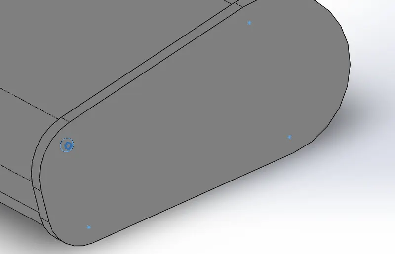
Patterns sketch in one or two directions at specific distance.
Linear Pattern:
Patterns feature, body in one or two direction in a line.
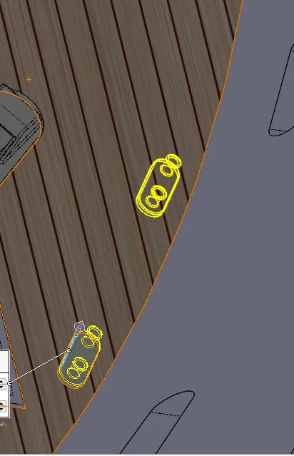
Circular Pattern:
Patterns feature, body in a circular direction.
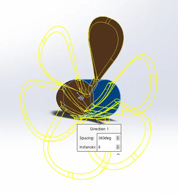
Loft:
The loft feature creates a shape by making transitions between multiple profiles and guide curves.This tool is very valuable for modeling complex surfaces.
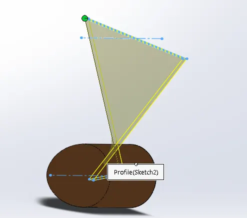
Fillet:
Creates a rounded internal or external face along one or more edges in solid or surface feature.
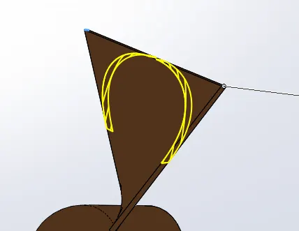
Shell:
Removes material from a solid body to create a thin-walled feature.
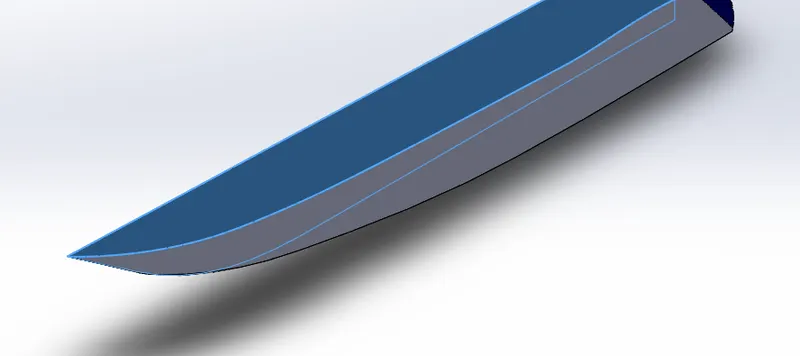
Dome:
It can add one or more domes to the selected planar or non-planar faces.
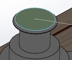
Sweep:
Sweeps a closed profile along an open or closed path to create a solid feature.
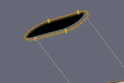
Trim Entities:
Trims a sketch entity to be coincident to another sketch entity.
Convert Entities:
Converts selected model edges or sketch entities into sketch segments.
Offset Entities:
Adds sketch entities by offsetting faces,edges,curves or sketch entities a specified distance.
Mirror Entities:
Mirrors selected entities about a centerline or planar reference.
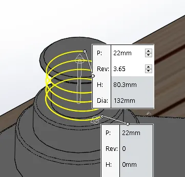
Helix/Spiral:
The Helix/Spiral tool can be cleverly used to generate 3D curves which can be then used as a sweep path. Ideal for creating springs.
Delete Face:
This option will remove the selected faces,leaving a void where the face or faces existed previously.
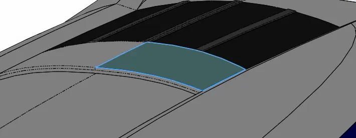
Projected Curve:
A projected curve is typically used either in sweeps and lofts as path or guide curve.There are two types of projected curves:
Sketch on Sketch:Use two sketches to make a singl curve.
Sketch on Surface:Use a sketch to project on a surface.
Split Line:
It divides a selected face into multiple separate faces.
Split:
We can split a sketch entity to create two sketch entities.
Surface Extrude:
Extrudes a sketch or selected sketch contours in one or two directions to create a surface features.
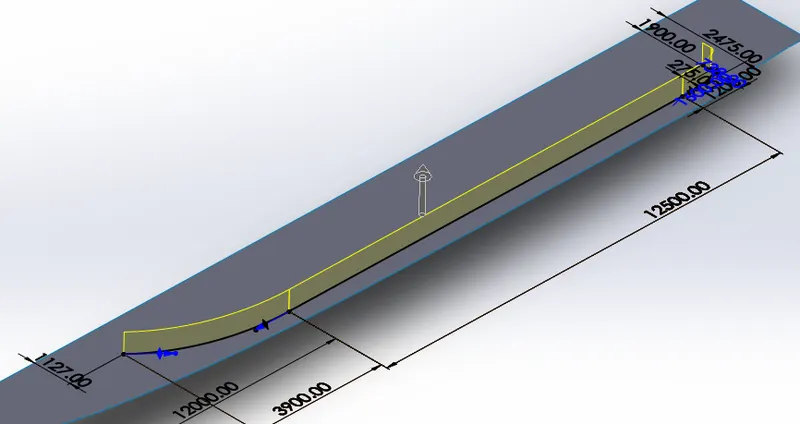
Surface Swept:
Create planes for sketching the sweep profile,sweep path,and if necessary,the guide curves.Sketch the sweep profile and path on the planes that you created.You can also sketch the sweep path on a model face or use a model edge for the path.
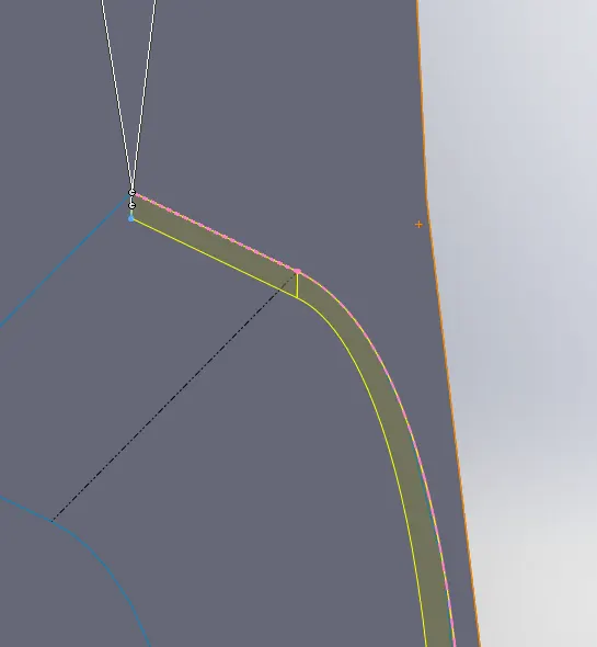
Surface Loft:
Create a lofted surface between two or more profiles or sketches.Specify start and end constraints and add guide curves to control the path shape.
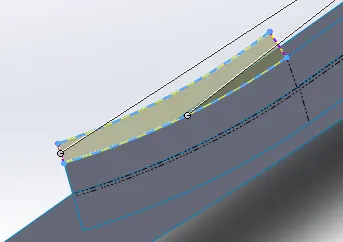
Surface Extend:
Extends one or more edges or faces on a surface, based on end conditions and extension type.
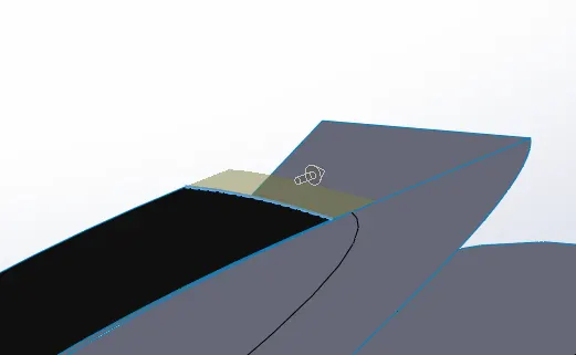
Surface Fill:
Patches a surface within a boundary defined by edges,sketches,or curves.We can use constraint curves to fill surfaces and adjust resolution control to improve surface finish.
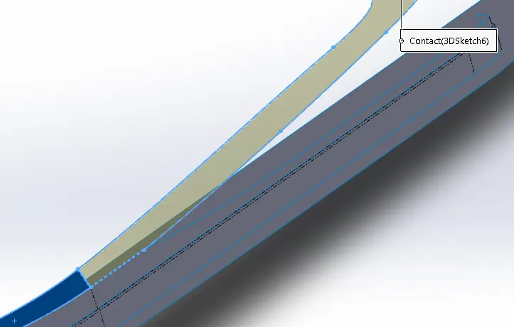
Ruled Surface:
Inserts ruled surfaces in a specified direction from edges.Tangent to surface,Normal to surface,Tapered to vector,Perpendicular to vector can be selected.
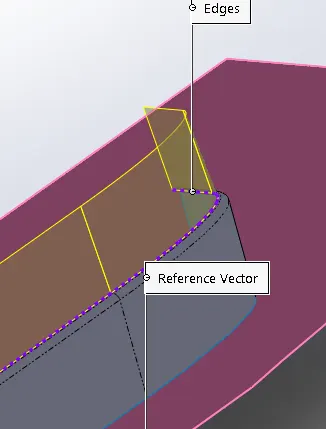
Surface Trim:
It trims the surfaces where a surface intersect with another surface,a plane or sketch.
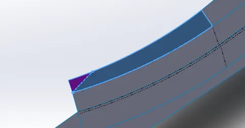
Surface Knit:
It combines two or more adjacent,non-intersecting surfaces into a single surface body.The surfaces must joint at an edge.If the resulting knit surface encloses a volume,We can create a solid body from the property Manager.
Surface Offset:
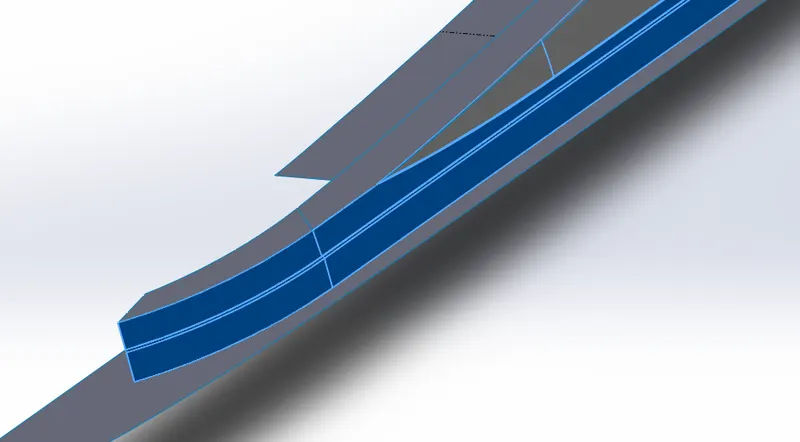
Offsets surfaces using one or more contiguous faces.This tool helps us to create an offset surface with gaps.
Mirror:
Mirrors features,faces,and bodies about a face or plane.
Assembly:
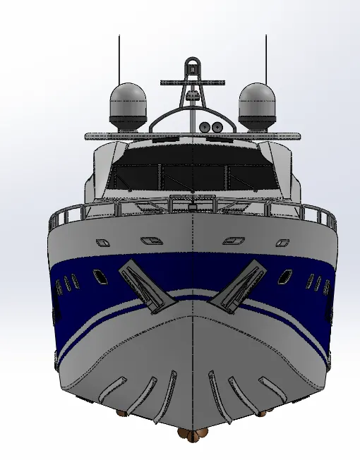
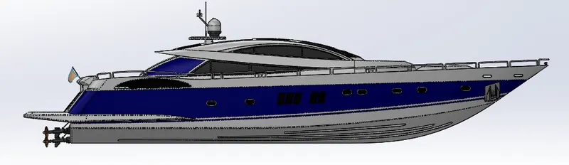
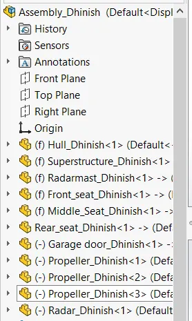
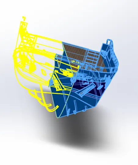
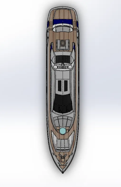
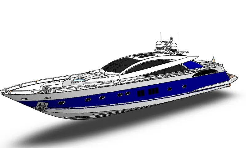
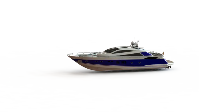
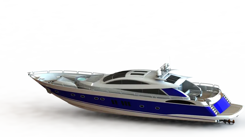
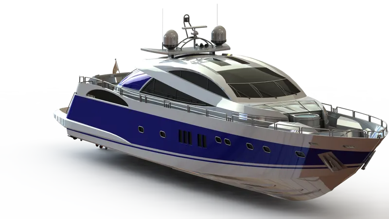
In the assembly part,all indvidual parts inserted into assembly tools of solidworks.Insert the hull part and fix it,then insert the superstructure and fix it on top of hull.Insert the radarmast and fix it on top of superstructure,Insert the front,middle, rear seat and place it on the hull.The garage door is set in with the helps of the mates.Insert three propeller seperately and add mates with the hull to assemble the propeller in the yacht.
Isometric View:
Front View:
Side View:
Top View:
Camera View:
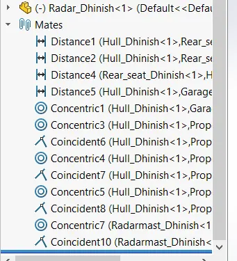
Mates Used:
Distance
Concentric
Coincident
Rendering:
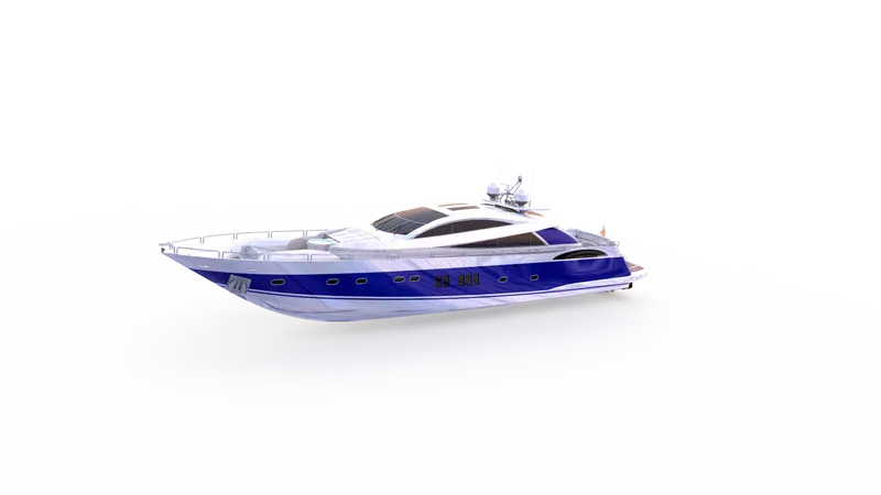
Rendering is the method of making with the reality accurate representations of the photorealistic model.In solidworks, rendering has been accomplished in two methods.The two manners as follows,
1.Photoview 360
2.solidworks visualize
Photoview 360:
Photoview 360 is a software solution from solidworks,fully integrated into the solidworks software to create photorealistic images directly from solidworks models.Photoview 360 can produce photorealistic images to add visual impact to presentations and documents.
Solidworks visualize:
Solidworks visualize allows us to leverage our 3D cad data to create photo quality content in the fastest and easiest way we can from images to animations,interactive web content,and immersive virtual reality.
Conclusion:
The components of the yacht are sketched and modelled in solidworks.
The components are placed into the setting of the assembly and assembled by applying the mates.
Using photoview 360 & solidworks visualize, the realistic image was rendered.