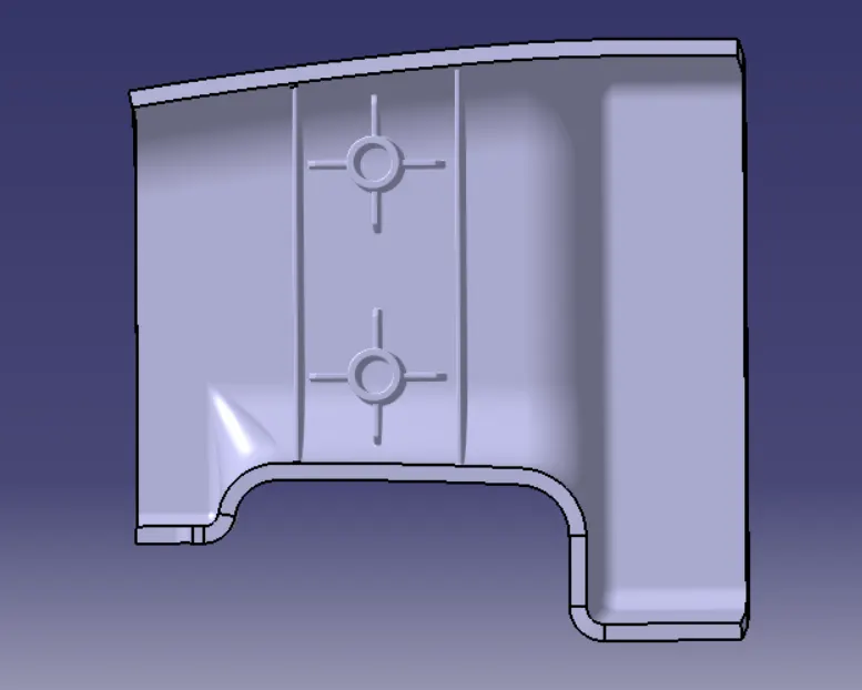
Week 9 - Attachment Feature Creation (Ribs & Screw Boss) - Challenge 1
AIM
To create the rib and screw boss for the Drill Handle.
REPORT
1. Creation of tooling axis
- At first we check the class A surface is ok by using the boundary option.
- After that we extract the base surface which identified as the best place for tooling axis to pass through.
- Create a point on the center of that surface.
- Draw a dummy line perpendicular to the surface passing through the point.
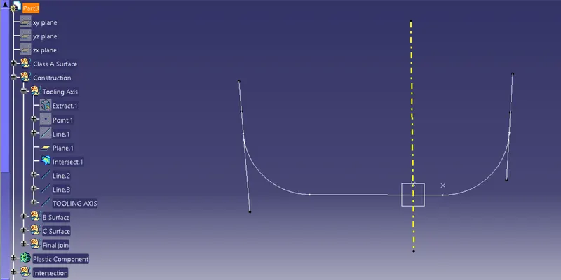
- Create a plane parallel to the curve and use intersection option to create the intersection line.
- Indentify the points or place which could cause trouble while moulding.
- Draw a line on both sides as below.
- Now using bisecting line method create a bisecting line passing through the point.
- This line is our tooling axis.
2. Draft analysis on class A
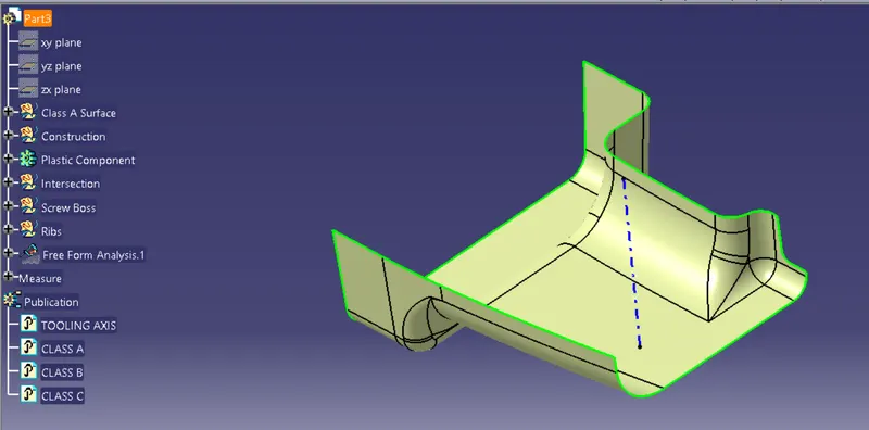
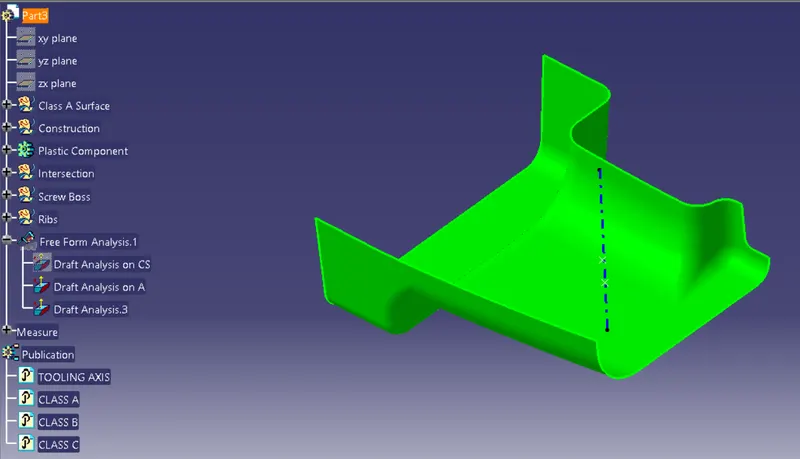
- Open the draft analysis toolbar.
- Click on the compass icon and drag and place the compass on tooling axis.
- Click anywhere on the body to run the analysis/
- From the image we can see that the class A clears the tooling parametrs.
3. Creation of B surface
- To create the B surface, first we offset the class A inside by 2.5mm.
- Check for any patches are formed on the surface, like,,
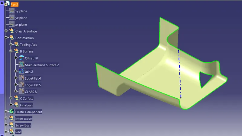
- Using the boundaries, multi section surfaces and join operation we create the B suface
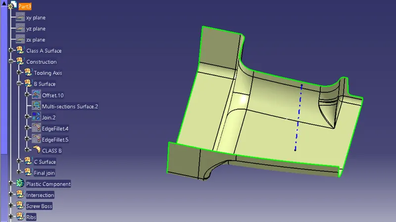
4. Creation of C surface.
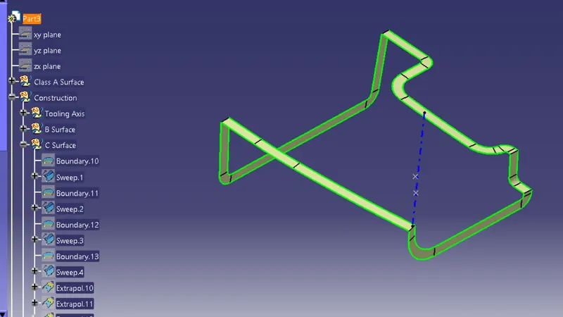
- Identify the sharp corners in the Class A surface.
- Accordingly we create multiple sweeps depending on the number of boundaries.
- Exrapolate al these sweeps.
- Trim them to get the C surface.
5. Final Join
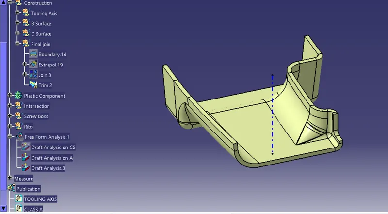
- At first join both the A and C surface.
- Then extrapolate all the sides of class B to a min distance.
- Then using the trim option, we join both B and A+C surfaces.
6. Creation of closed surface.
- Open the part workbench.
- Click on closed surface option.
- Click on the object and the final body is generated.
7. Creation of Ribs
- Extract the top surface of the final body.
- Create a point on the center of the surface.
- Create a plane normal to curve
- Create a sketch of the first rib
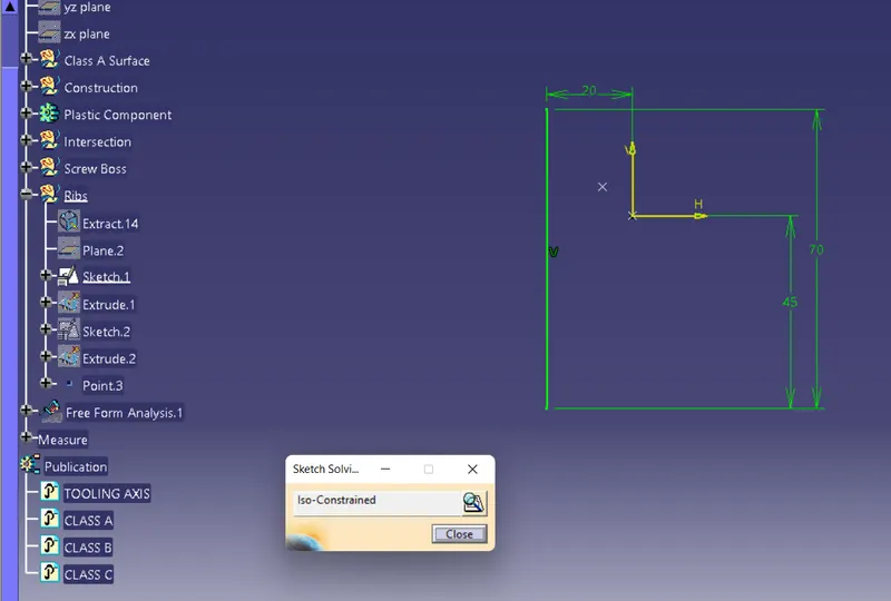
- Extrude the line from the sketch to 12.5 mm since the rib depth is 5 times the thickness. Also extrude the line downwards of 1mm.
- Apply thickness to this rib which is typically 40% of the nominal wall at the base, i.e 1mm.
- Apply draft to the rib for 0.5 degrees.
- Apply fillets to the rib for 0.25 radius.
- Then union trim the rib to the main body.
- Then create another rib at a particular distance in this case, following the same steps above.
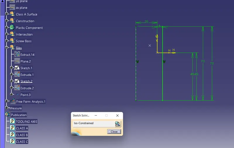
Design rules to follow while creating ribs are:
- Min draft: 0.5mm per side
- Rib thickness-: 0.4*t
- Min thk on tip of rib: 0.75mm
- Max Rib fillet radius: 0.25mm
- Rib height: less than 5* nominal wall thickness
- Rib should be spaced with a height to width ratio: 3:1 or 2:1
8. Creation of Screw boss
The guide lines are:
- The outside diameter of boss should remain within 2.0 to 2.4 times the outside diameter of the screw or insert.
- Min draft: 0.5mm on wall of boss
- Thk: 40% of nominal wall of base
- Height to dia ratio: 3:1
- Boss gussets must meet rib guidelines
- Max fillet radius: 0.25mm
- Create a sketch for the screw boss as shown:
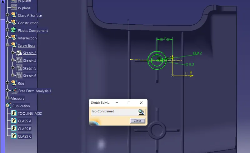
- Pad the sketch for 12.5mm and 1mm inside
- Give draft for 0.5 degrees.
- Create a support for the screw boss following the below sketch.
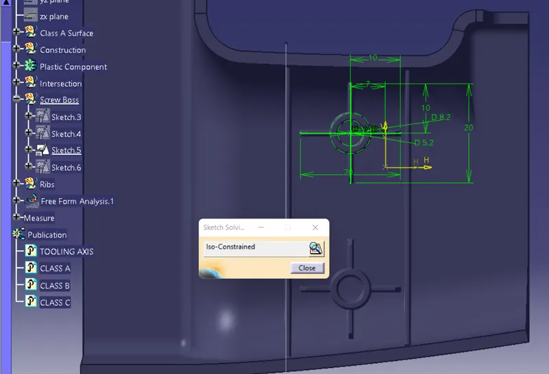
- Pad it to 7mm and 1mm inside. Also apply thick option.
- Give draft for 0.5degrees.
- Give a chamfer for every edge.
- Union trim this support to the screw boss
- Apply edge fillets.
- Union trim this to the main body.
- Similarly create one more screw boss.
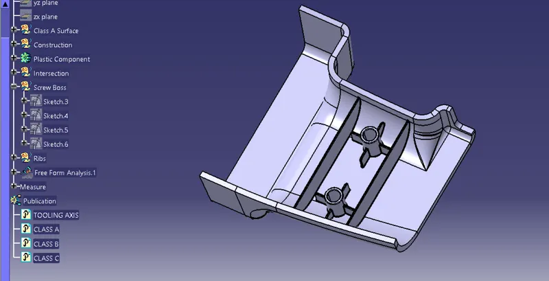
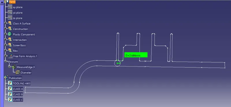
9. Intersect
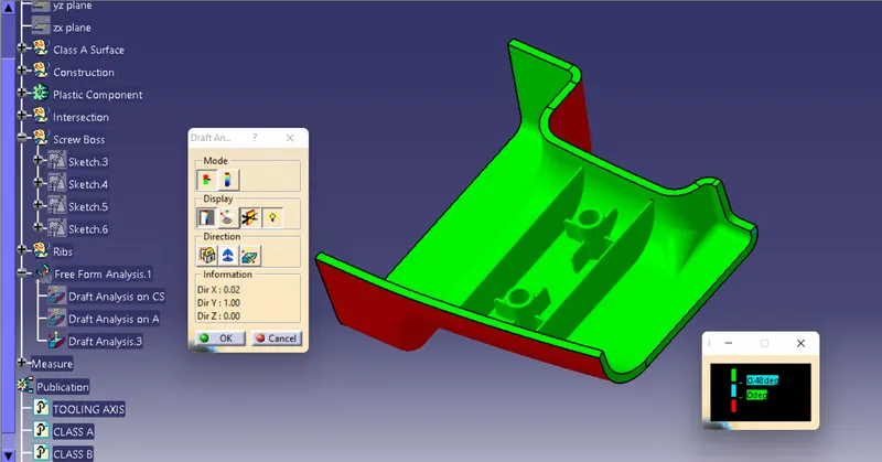
10. Draft Analysis on Closed Surface
- Draft analysis is done on the finished surface.
- The design clears the draft analysis.
RESULTS
1. ISOMETRIC VIEW
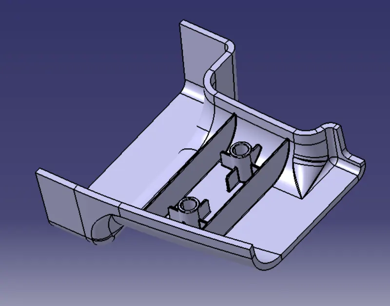
2. FRONT VIEW
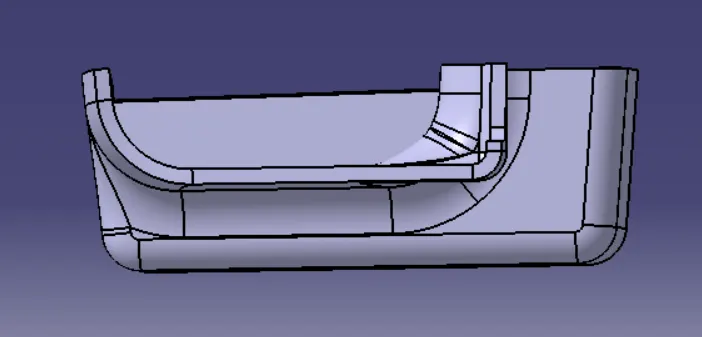
3. SIDE VIEW
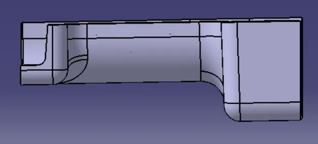
4. TOP VIEW