Week 9 - Attachment Feature Creation (Ribs & Screw Boss) - Challenge 1
RIBS AND SCREW BOSS DESIGN:
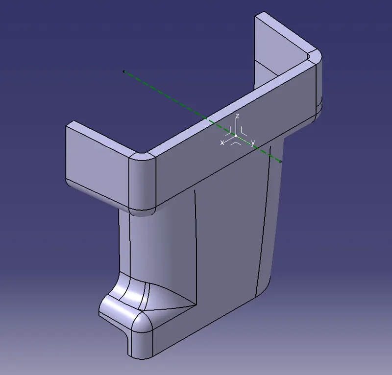
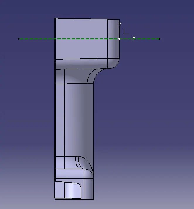
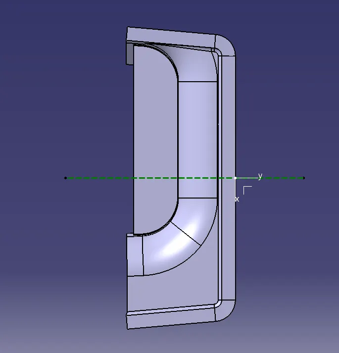
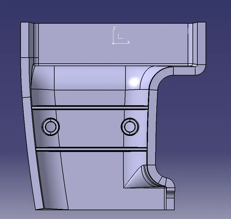
The images of the complete part in different orientations are shown below
Isometric view
Front view
Top view
Left side view
Tooling axis: -
Tooling axis is created using a reference point from an extract of a planar face of the given Class A.
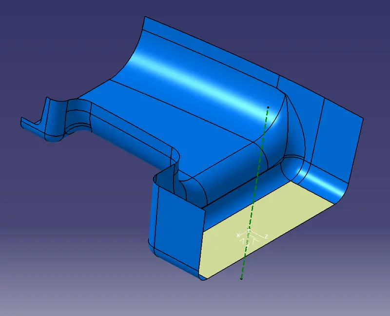
Draft analysis of final part: -
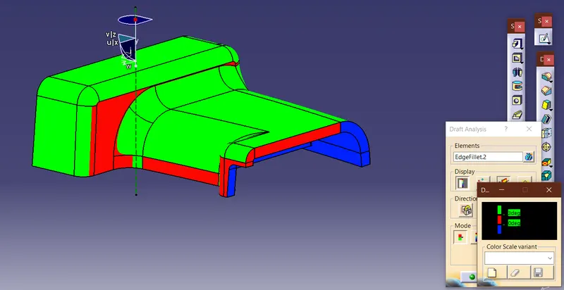
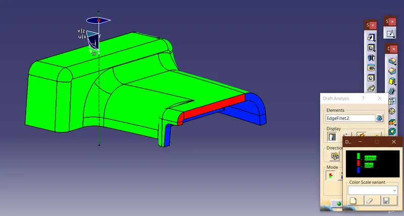
We see that Class B has negative draft which is acceptable, but Class A and Class C have regions which have draft less than 3-degree. The draft result of Class C is due to the 90-degree angle which was given to Class C with respect to Class A. For the Class A result, let us check the draft analysis of Class A.
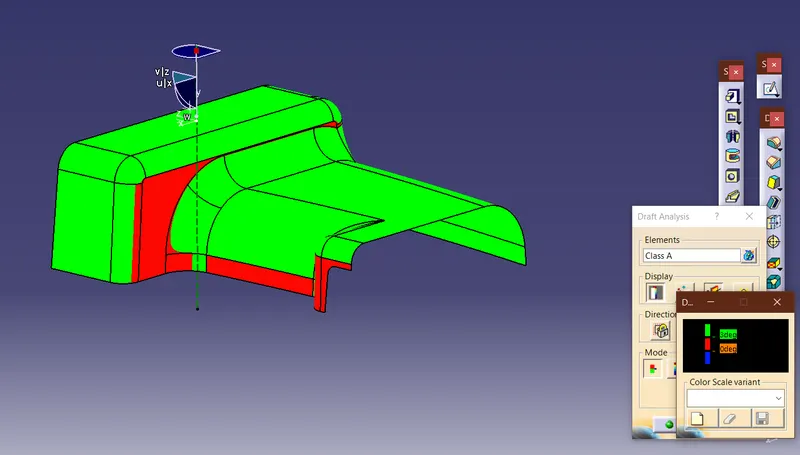
The draft analysis of Class A produces the same results as the draft analysis of final part, this value of draft which is lower than expected can be because of two reasons
1. The tooling direction is incorrect
2. Given Class A has to be modified to give draft more than 3-degrees
Next step is the verification of draft angle of the ribs and screw boss features.
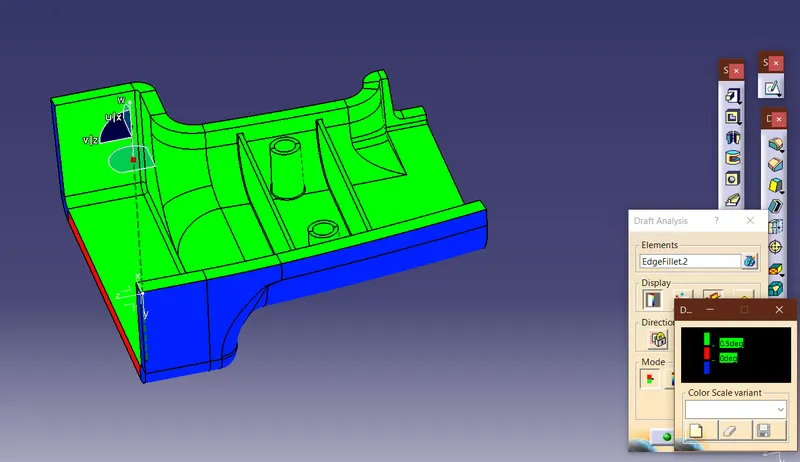
Here, we can observe from the results that all regions of ribs and screw bosses are above the 0.5-degree draft. Thus, the design of these features is acceptable.