Week -2
AIM:
1. Make a Simulink model of doorbell as per conditions.
2. Use a thermistor to sense the temperature of a heater and turn on or turn off the fan as per conditions.
MODEL LINK OF DOORBELL:
https://drive.google.com/file/d/1a_Y-JvF3yZnziNYltEZcu3JOq9Mp2f52/view?usp=sharing
MODEL IMAGE:
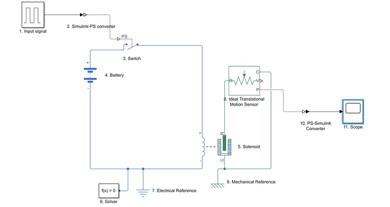
EXPLANATION:
1. Input singal of the doorbell. Pulse generator block is taken for the input signal.
2. Simulink-PS converter converts simulink singal/input to a physical signal so that is can be read by simscape block.
3. PS switch is a switch in simscape which is controlled by an external physical signal.
4. This block models a battery of which parameters like voltage, internal resistance can be changed.
5. This block implements the electrical and mechanical characteristics of a solenoid. When current runs through the circuit for a brief time interval, as the working of solenoid a magnetic field is produced and plunger moves towards case.
6. Solver block defines the solver configuration required for simulation of a physical network.
7. Electrical reference/electrical ground is necessary for an electrical network in simulink.
8. Motion sensor to get the movement of the solenoid plunger. The sensor is ideal as it does not account losses such as due to inertia and eddy currents.
9. As in electrical network, mechanical network in simulink also requires a reference/ground.
10. PS-Simulink converter converts physical signal of simscape to simulink signal.
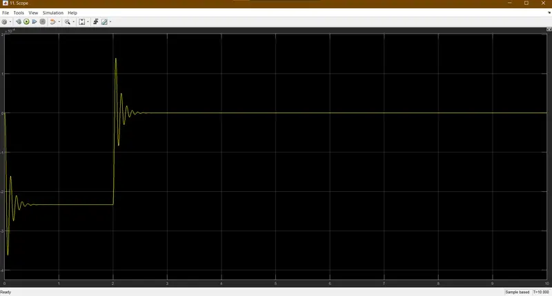
11. Scope records the output of the input singal, which in this case is the movement of solenoid plunger measured by motion sensor.
OUTPUT:
MODEL LINK OF THERMISTOR:
https://drive.google.com/file/d/1TnxN9qqy6b5AKUYasasFf1GbznLQ7bIQ/view?usp=sharing
MODEL IMAGE:
EXPLANATION:
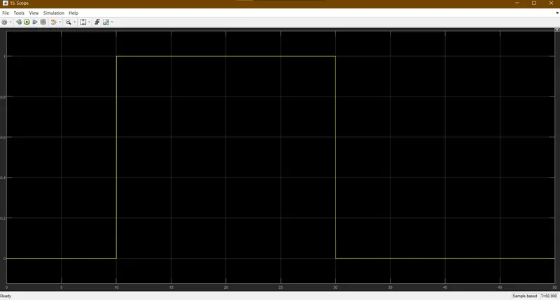
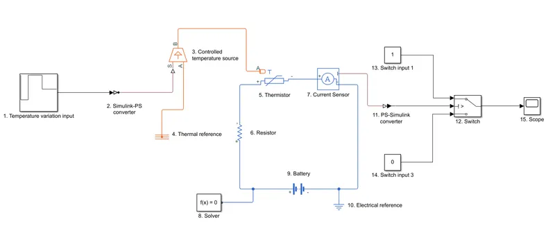
1. The temperature variation is used as a signal with the help of repeating sequence stair block.
2. Simulink-PS converter is used to convert simulink signal to physical signal.
3. This block takes an input signal and applies the signal variation to temperature variation. Regardless of the heat flow, the temperature is maintained.
4. This block provied the thermal network with a reference/ground.
5. This block represents a Normal Temperatre Condition thermistor, the resistance changes according to the change in temperature value. This is used to detect/sense the temperature change via an electrical network.
6. A simple electrical resistance of 1 ohm is connected in series to the thermistor.
7. Current sensor measures the current in an electrical network/circuit and shows it as a physical signal. It is connected in series with the thermistor.
8. To solve the physical network and to simulate it, a solver block is required.
9. Battery block represents a battery in the circuit giving electrical power to the circuit at a defined voltage at defined internal resistance.
10. This block provides a reference/ground for the electrical network.
11. PS-simulink converter converts the physical input to simulink output.
12. A simulink switch take the input from input port 1 if the input at input port 2 satisfies a defined criterion, else it takes input from input port 3.
13. This block is connected to input port 1 of the switch.
14. This block is connected to input port 2 of the switch.
15. Scope records and displays the signal output from the switch as a graph.
OUTPUT: