Week 9 - Attachment Feature Creation (Ribs & Screw Boss) - Challenge 1
DESIGN OF THE DOOR HANDLE WITH ENGINEERING FEATURES INCLUDES RIBS AND SCREW BOSSES
AIM:To create the door handle component by generating the class B and class c surfaces with the aid of class A provided and cfreating the B side features include the ribs and the screwbosses by folowing the design parameters.
Procedure followed:
The following steps are included while designing the door handle with B side features
- Tooling axis creation
- Draft analysis of class A surface
- Class B surface generation
- class C surface generation
- Final trim
- Solid body generation
- Draft analysis of the solid body
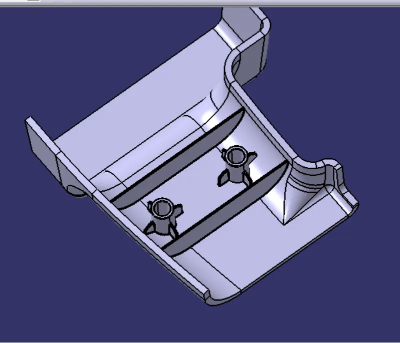
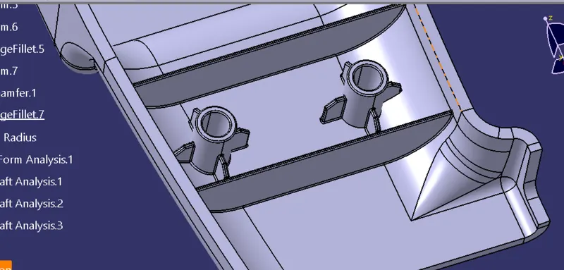
- Ribs creation
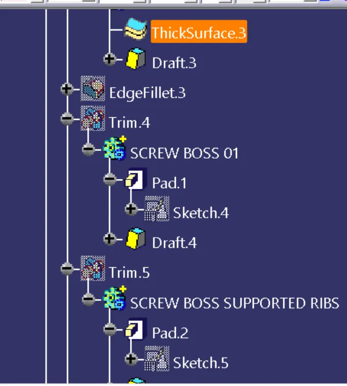
- Screw boss creation
- Draft analysis of the solid body with B side features
Class A surface:
Class a surface is an asthetic surface with a polished surface which will be visible for the customers, and with the aid of the class A we could be able top geneate the class B and class C surfaces
Class B surface:
class B is an engineering surface where the B side features include the ribs, screw bosses , doghouses are located
Class C surface:
Class c is an intermediate surface between the class A and class B surfaces.It is generated by sweep feature either with reference surface or with the draft direction.If the generated C surface is parallel yo the tooling axis then we make the aid of the draft direction or else proceed with the reference surface
Commands deployed:
Surface commands:
- Extract
- Boundary
- Extrapolate
- Sweep
- Join
- Trim
- Intersect
- Multi section surface
- Surface extrude
- Multi extract
Part Workbench commands:
- solid surface
- Thicken
- Pad
- Draft
- Fillet
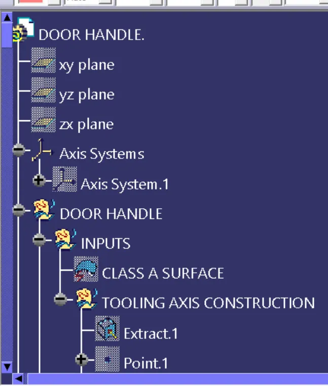
1.TOOLING AXIS CREATION:
In the case of the door handle component potrait the component in various views and find whether any view is suitable for manufacturing the component in single go So for this case we employed the bisecting method to generate the tooling axis
In the bisection method extract the best view surface and create the intersect and extent the two lines and create a line of bisection with the help of two lines and the point so thus creates the tooling axis
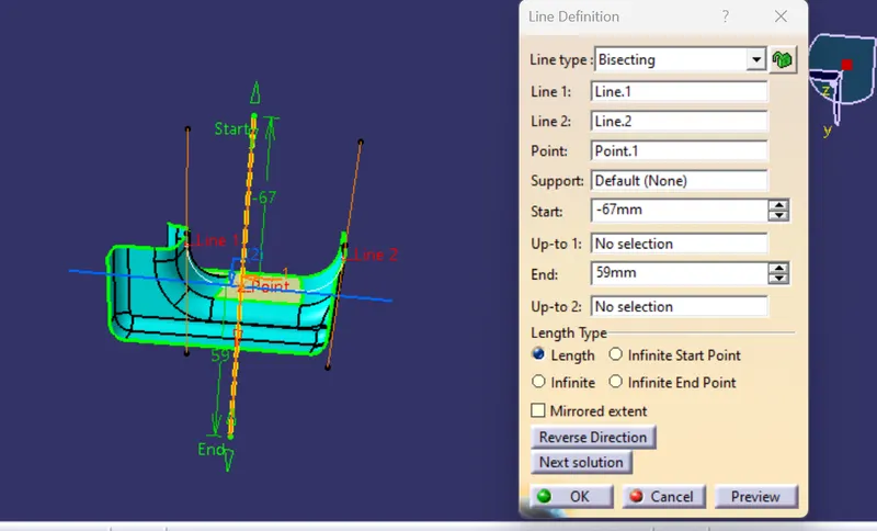
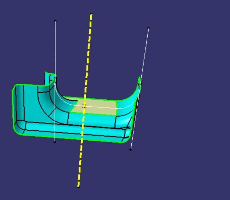
After creating the tooling axis perform the draft analysis on class a surface to check whether all the surfaces are provided with required draft
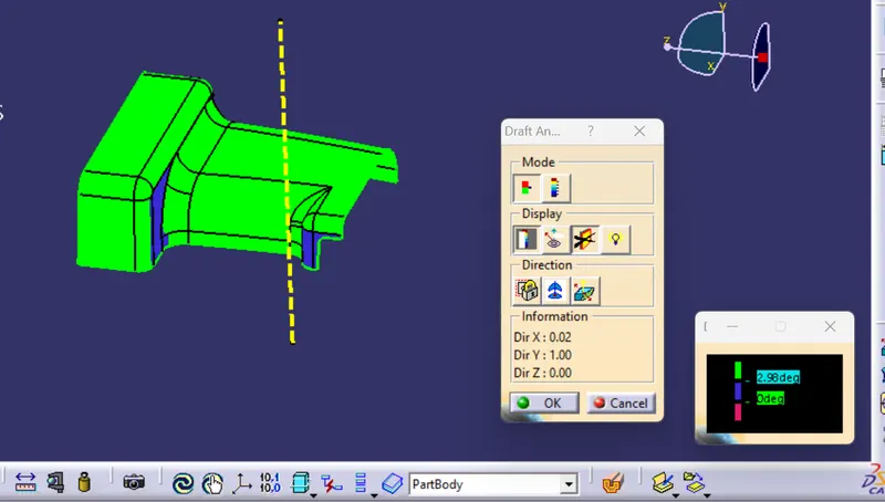
Almost all the surfaces of class a are claering the draft analysis behalf of 3 blue colored surface which means their might be some problem in the class a surafce and it need to be modified. So contyoinue with the class b surafce creation
Class B surface creation:
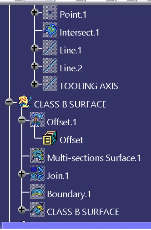
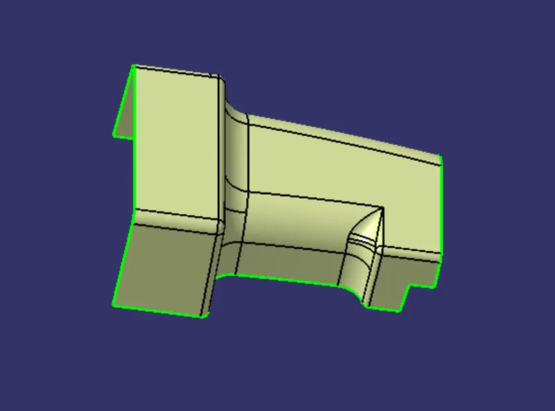
Class B surface always lies beneath the class A surface with an offset value of less then or equal to 3mm .So offset the class A to an offset value of 2.5mm
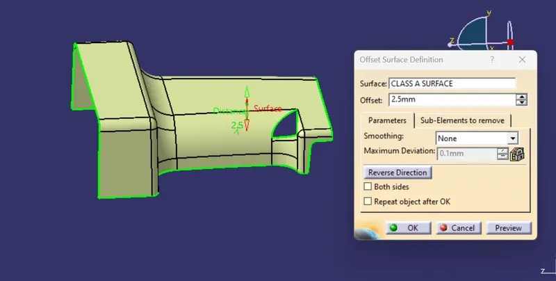
So after offsetting the class a surfa e there may be a generation of a pathch so we need to work on it to complete the generation of entire B surafce
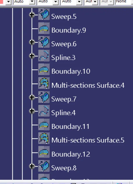
So we use the multisection surface feature to close the patch.
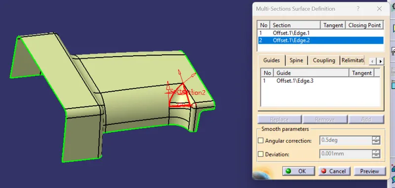
Now join the two surfae using the join command to form the entire B surafce .
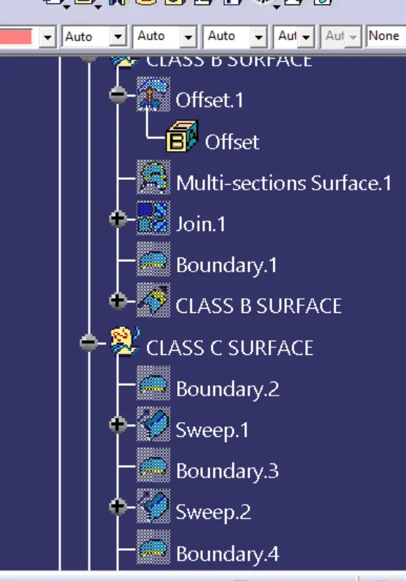
Class C creation:
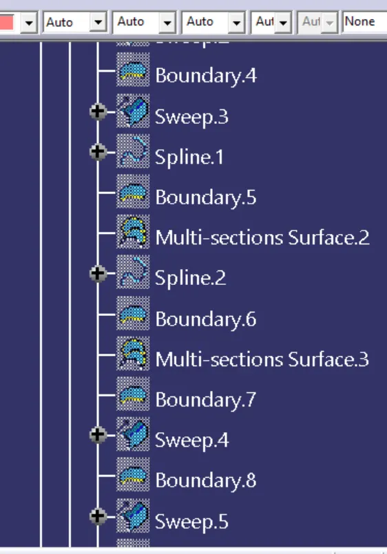
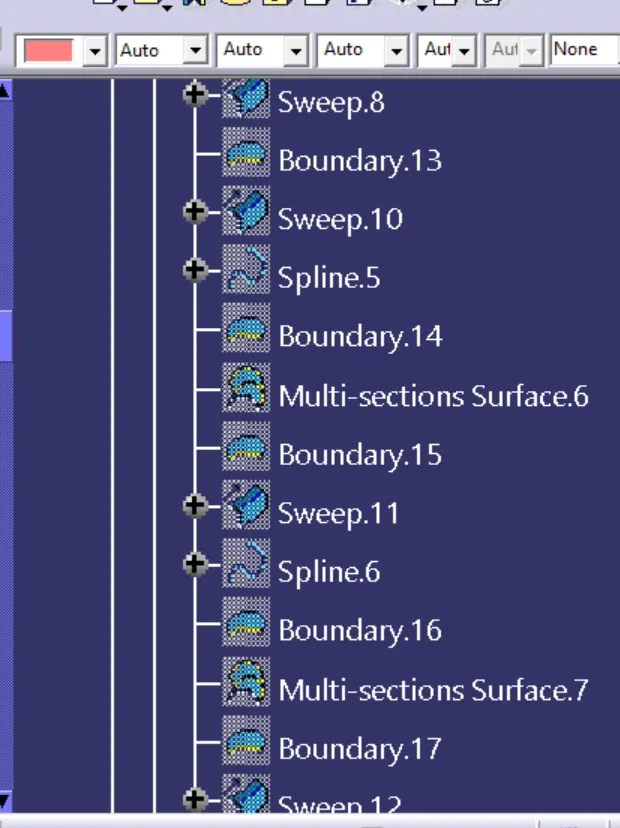
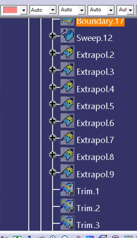
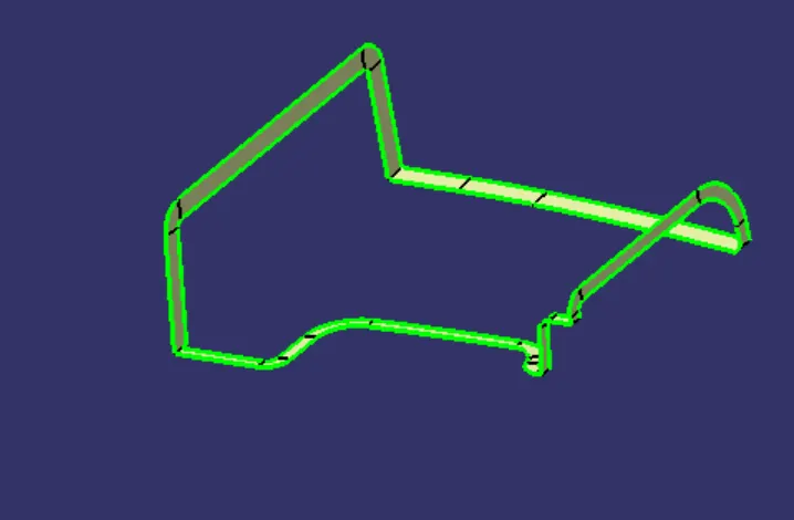
With the aid of the class A surface create the class c surface by using the sweep feature .If the generated C surface is parallel to the tooling axios create the sweep along the draft direction with a draft of 3 degrees or if the suface is perpendicular to the tooling axis then create the sweep using the reference surface option then exrtrapolate the connecting surafces and trim the surface together ang join them all together to form the class c surafce
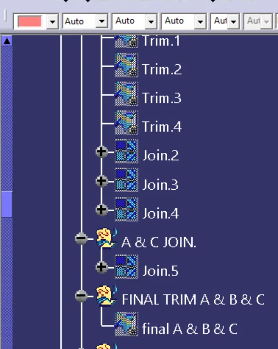
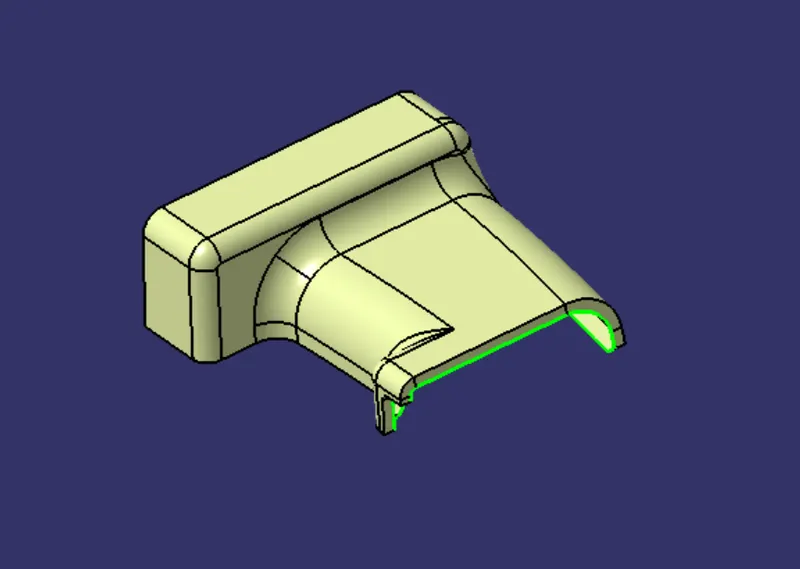
Now join the class A with the Class C surface
Final trim:
Now trim this join the class B surface
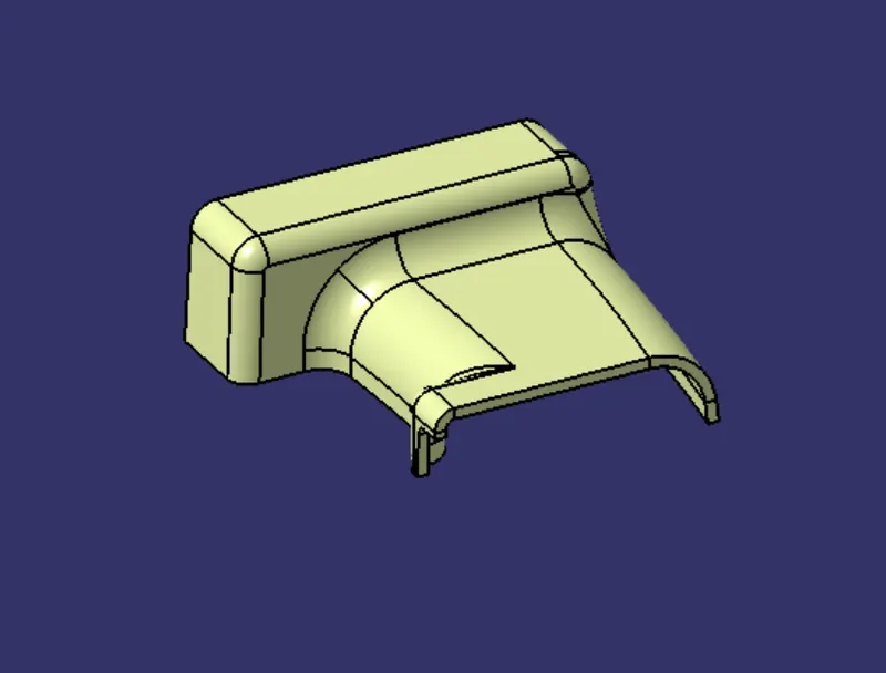
Now performm the draft analysis on this surface check whether it is clearing or not
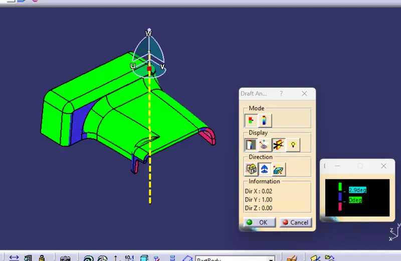
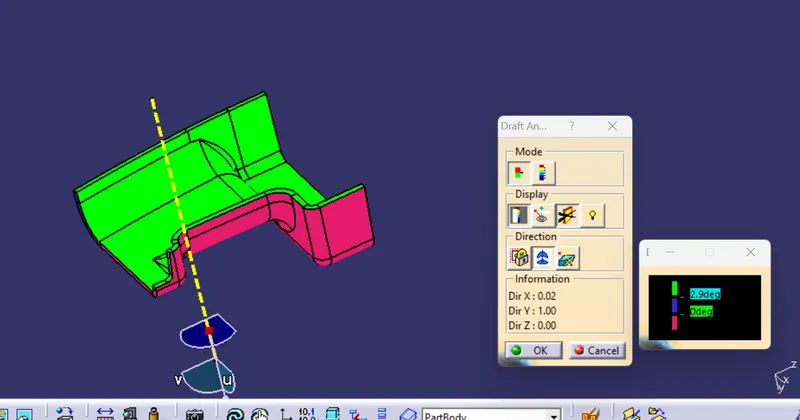
So some surfaces are claering in the class A draft and some other in the class B draft where the some blue color surfaces shows thet they might have some problem with the class a surface and they can't be able to claer the 3 degree draft so we need to continue irrespective of lowering the draft as the main modifications to be done ogn the class A surface
Solid surface generation:
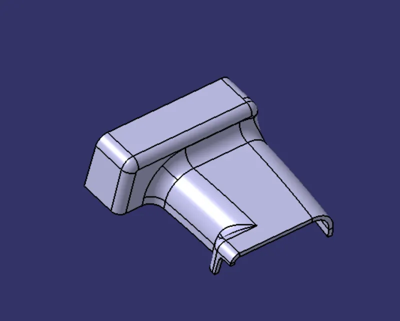
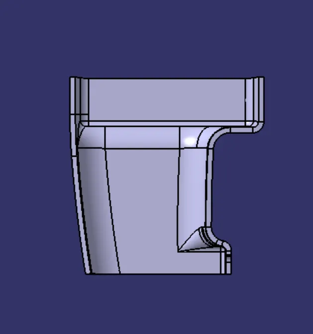
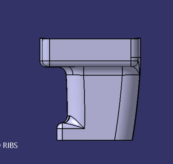
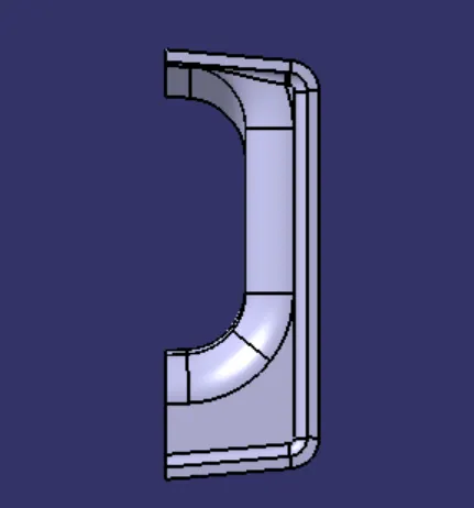
After performing the draft analysis anbd if you are satisfactory with the draft analysis then go to the part workbench and apply the solid surface feature to the final trim surface
ISOMETRIC VIEW
RIBS CREATION:
Ribs provides a mean of strength and stiffness to the molded component without increasing the overall wall thickness
Ribs basically facilitates:
- Locating and arresting the components of an assembly
- Providing alignment in mating parts
- Acts as a guides or stops in mechanisms
Design parameters:
- Draft: 0.5 Degree per side (minimum) and maximum upto 1.5 degrees
- Thickness of ribs: 40 to 50% of wall thickness
- Height: ≤ 5 times the wall thickness
- Spacing (for more than 1 rib): 3:1- steel height/width ratio (maximum). h/w =3 or2(preferred) where h is the height of the rib and w is the space between two ribs.
- Minimum thickness at the tip: 0.75mm
- Rib fillet Radius: 0.25mm max or 0.125*thickness of the component
- Rib root thickness should not be more than 30% of the wall thickness.
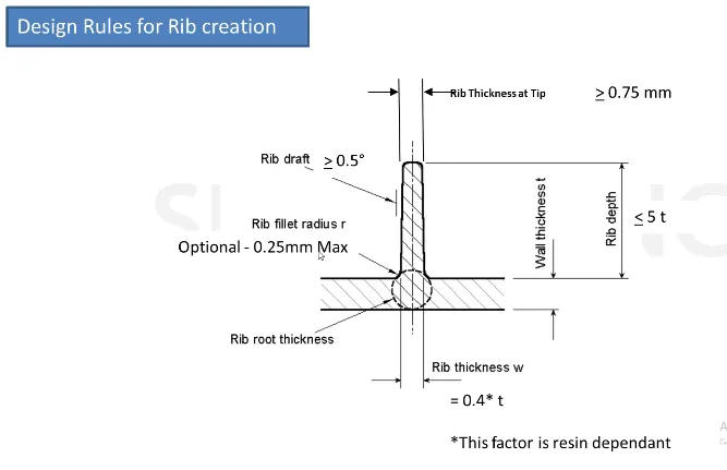
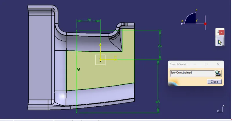
Extract the surface and create a plane and select the plane for the sketch and draw an iso constrained line and extrude the line to a height of H = 5*2.5=12.5mm
Now thicken the extruded surface to 1mm as w= 0.4*2.5=1 mm
Now apply the draft to the surface as refernce to the extract and using the pulling direction as tooling axis to a draft of 0.5 degrees on each side.
Now union trim the rib with the main solid body of the door handle
Now apply the fillets of 0.25mm on each side
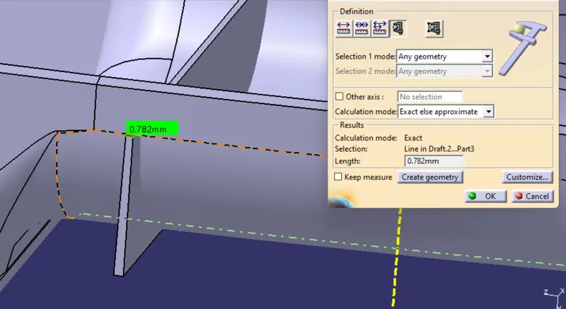
Find find the rib root thickness by taking the intersection of the rib and create a tritangent circle and find the diameter of the circle which must not be 30% more than wall thickness
The thickness at the top is 0.782 mm
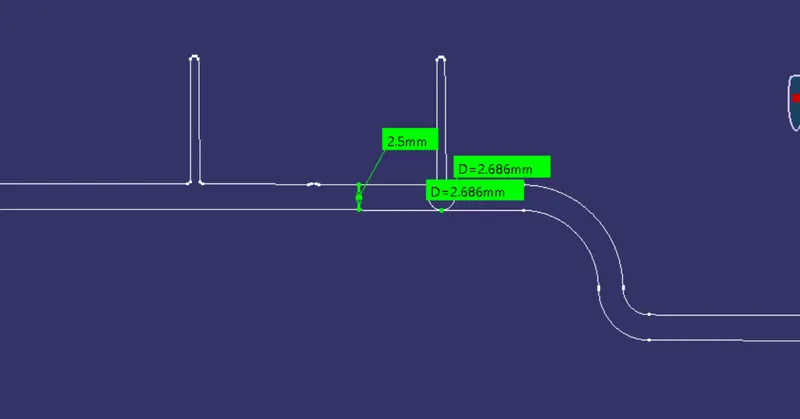
so the rib root thickness is 2.686mm so 30%* wallthickness =0.3*2.5=3.25 mm
So rib root thickness is satisfified as 2.686 mm < 3.25 mm
Now apply the same design parameters for creating the rib 02
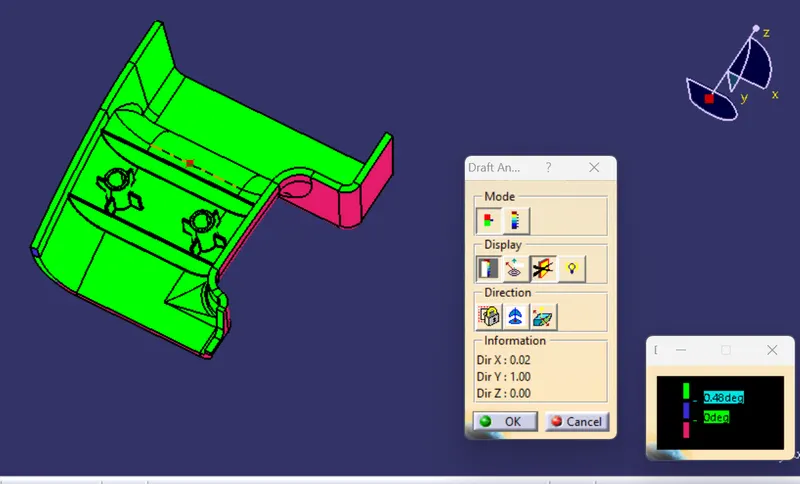
After all apply the draft analysis and the ribs can claer the draft at 0.48 degrees
Screw boss creation:
Screw bosses generally find use in many part designs as points for attachments and assembly . The most common variety consists of cylindrical projectiobns with holes designed to recieve screws , threaded inserts or other type of fastening hardware
Design parameters:
- The outside diameter should be 2 to 2.4 times the inside diameter
- W= 0.6*T
- Draft 0.5 Degree on both inside and outside walls of the screw boss.
- Height to diameter ratio – 3:1
- Radii(fillet) – 0.25mm(maximum)
- Boss Gussets must meet rib guidelines
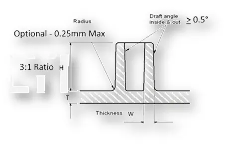
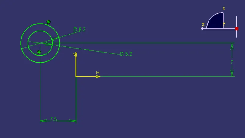
So pad the sketch to a height of H= 5*2.5= 12.5mm so better to extend the pad to the other side a little bit of 20to 3mm so that the proper assembling will be possible with the main body part
Now apply the draft of 0.5 degrees on inside and outside diameter faces
Now crate the ribs for supporting the ribs by following the rib design parameters
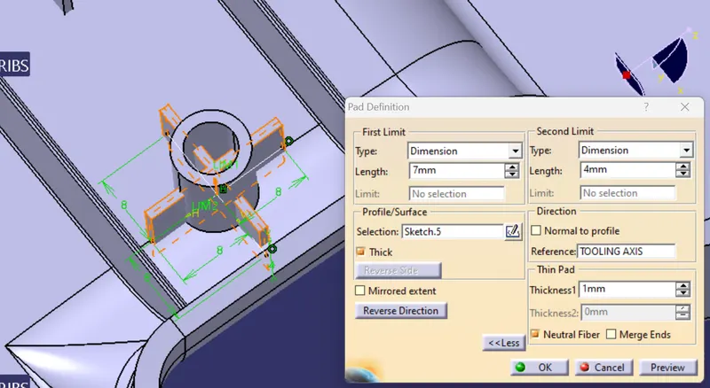
So the height of the rib would be 60% of the height of the screw boss
apply the draft of 0.5 degrees to all over the sides of the ribs
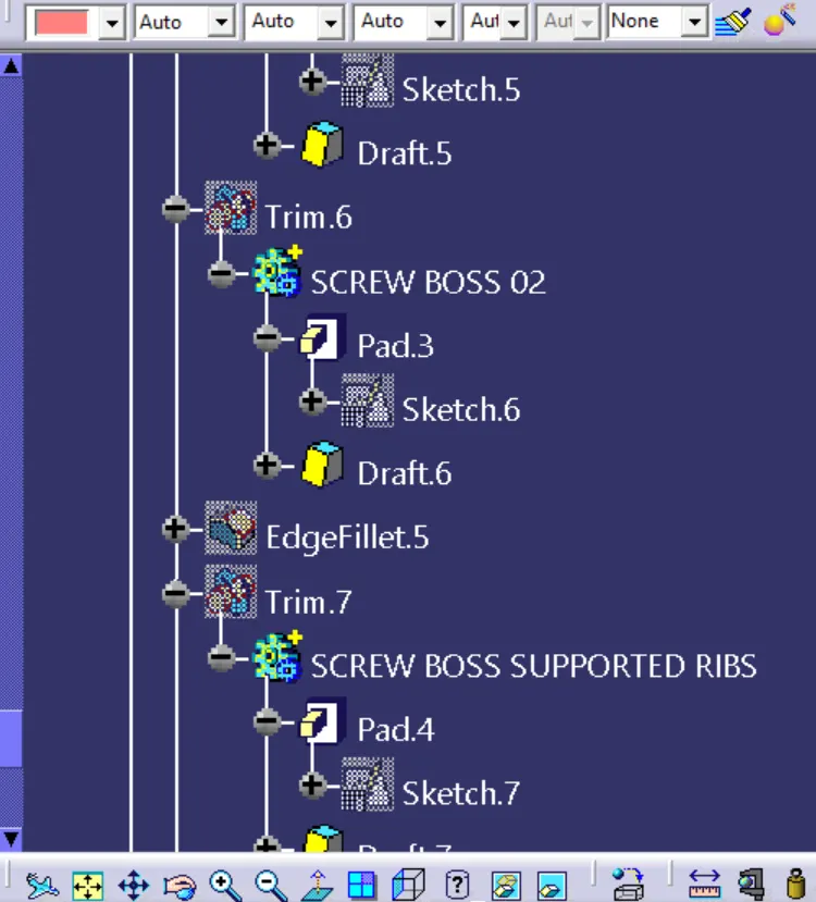
Use the boolean operation of union trim to assemble the ribs and the screw bosses to the main solid body
Now generate the other screw boss at a certain distrance
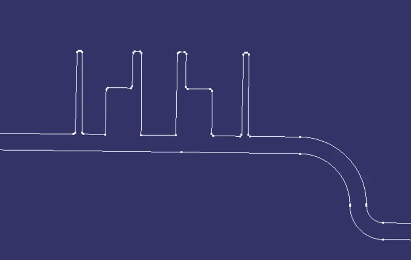
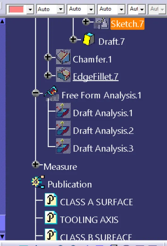
Now perform the draft analyiss of nearly 0.5degress to check whether all theB side features are clearing the draft analysis or not
Conclusion:
I have created the tooling axis using the given CLASS-A surface and created B side Features on the door handle solid body. Also performed draft analysis on both Class-A surface and Final part body with B side features and submitted the report in the box and submitted the cat part in the dialog box using browse option
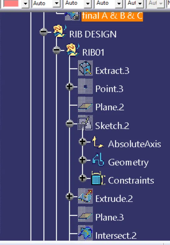
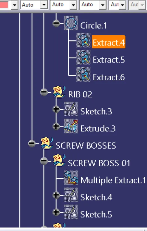
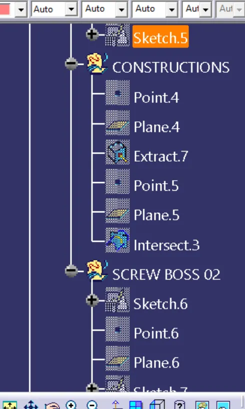
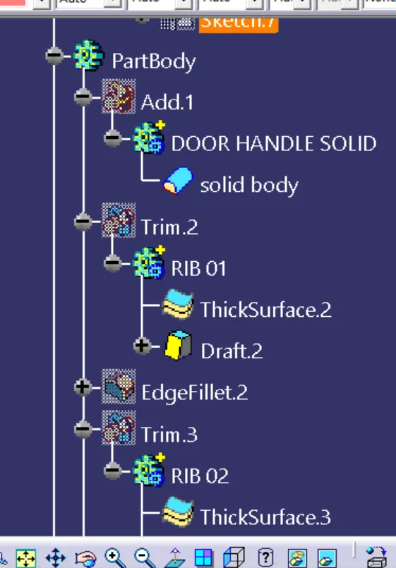
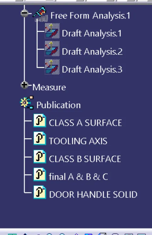
Tree structure: