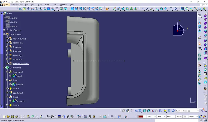
Week 9 - Attachment Feature Creation (Ribs & Screw Boss) - Challenge 1
DOOR HANDLE
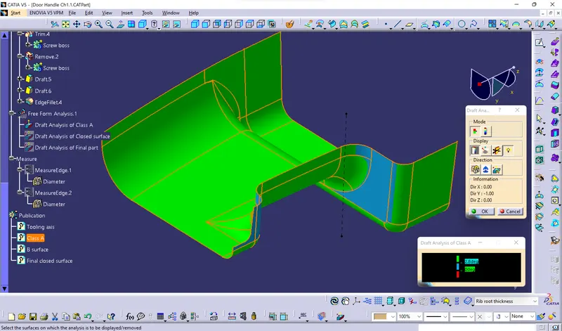
NOTE- The draft analysis of Class A surface shows blue color patch in it. And this is due to the issue in the input Class A surface
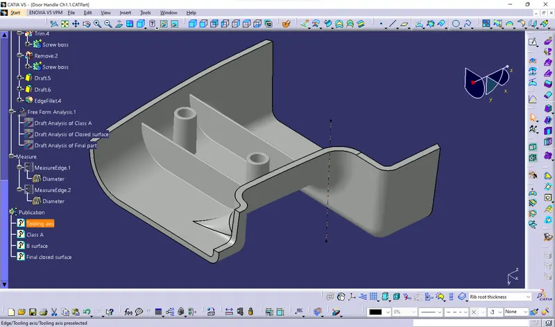
Tooling axis-
Generally, the part component that we design must be toolable or manufacturable. As we know that some exterior and most interior parts of automotives are made of plastics. In that approximately 80% of them can be manufactured by Injection molding. Injection molding have two halves- Core half and Cavity half, in which one is movable and the other one is fixed. To be manufacturable, all faces of the part component must clear the main tooling axis direction and there are exception in which sidecores are used additionally if holes or slots are present in the part component. Tooling axis direction is the direction in which the core half and cavity half opens.
There are three ways to find the tooling axis direction:
1. X, Y, Z axis method
2. Normal to surface method
3. Bisecting method
Generally if holes or large flat surfaces are present in the part component, the normal to them will be the direction of tooling axis.
In this door handle component, I have used normal to surface method to find the tooling axis direction.
Tooling axis direction of Door handle:
Draft analysis-
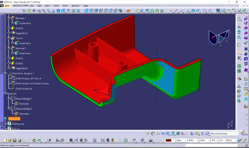
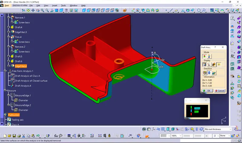
Draft analysis is a technique that is used to analyze whether the part component that we designed in catia part workbench can be manufacturable based on the draft condition applied.
Ideal draft value of part component- 3 degree
Minimum draft value of rib- 0.5 degree
Draft analysis of Class A surface:
Draft analysis of final part:
Design rules of Ribs, Screw bosses that is followed in this design-
Ribs
Wall thickness of part- 2.5mm
Width of rib- 0.4*Wall thickness = 1mm
Height of rib- 5*Wall thickness = 12.5mm
Spacing- (Assumption) 25mm
Draft- 0.5mm
Fillet radius- 0.25mm
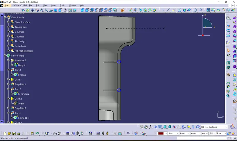
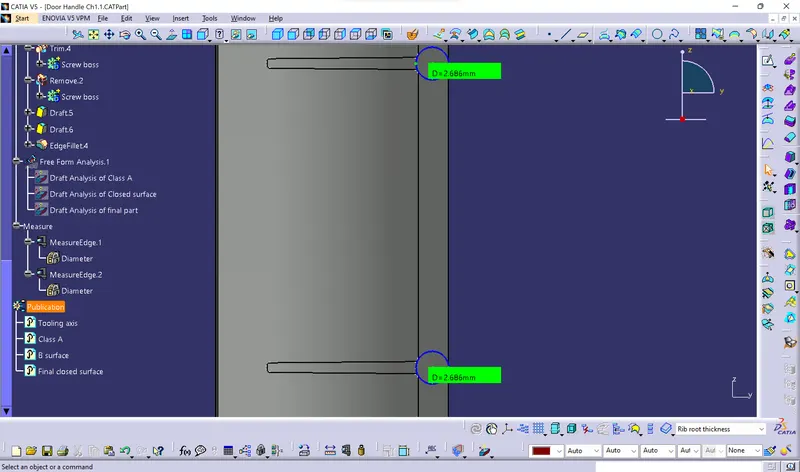
Rib root thickness- 30% deviation in the wall thickness
Screw boss
Diameter- 5.2mm
Height- Ratio of height and diameter is 3 = 15.6mm
Draft- 0.5mm
Fillet radius- 0.25mm
Rib root thickness-
Final part component in various orientations-
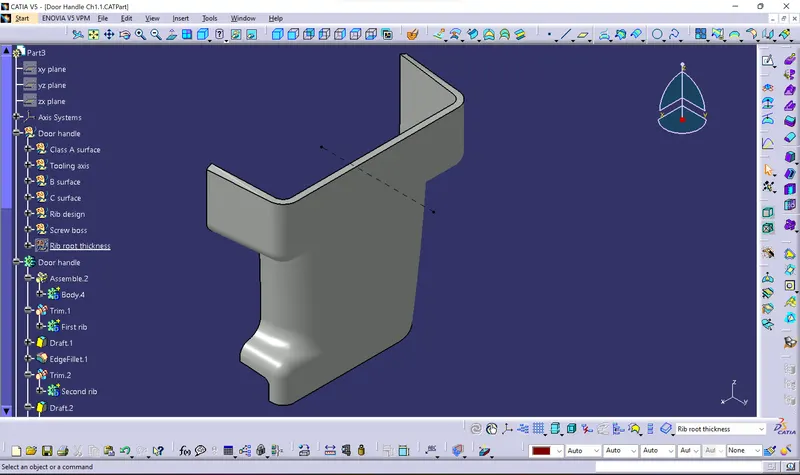
Isometric view
Front view
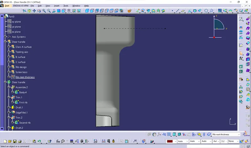
Back view
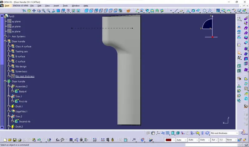
Side view
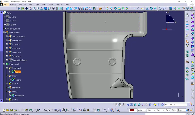
Top view
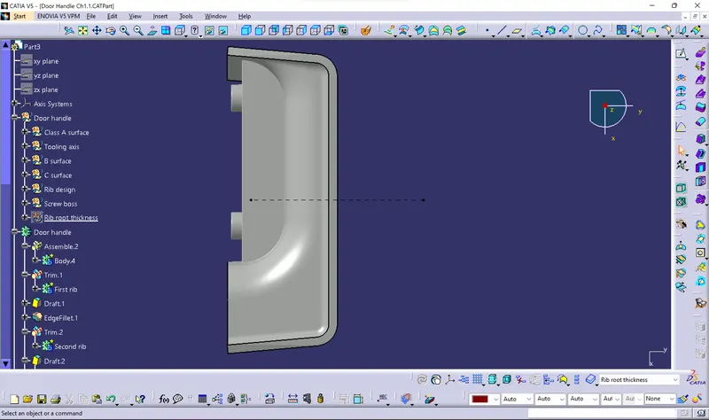
Bottom view