Week 9 - Attachment Feature Creation (Ribs & Screw Boss) - Challenge 1
Answer: Report on the draft analysis of Class A surface and Created soild model out of it
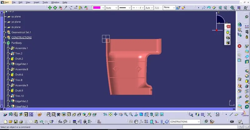
Given Class A surface:
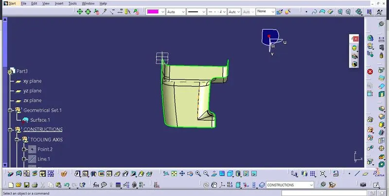
Step 1: Check the connectivity of the A surface ensure that there is no gap between the component.
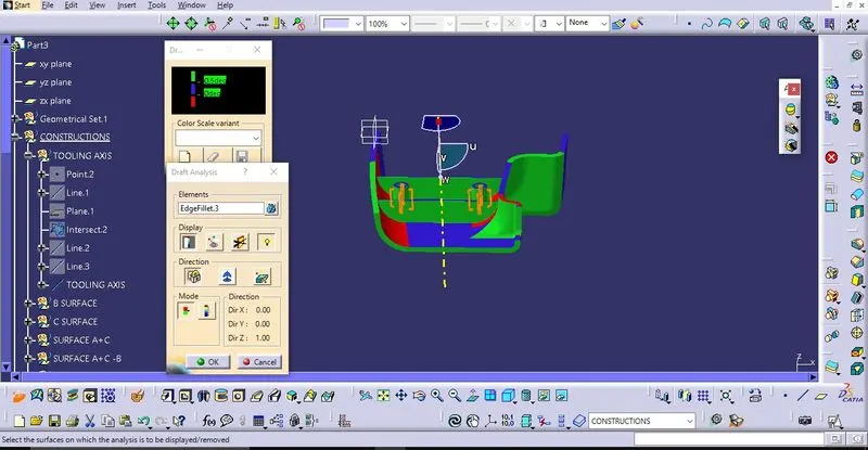
Step 2: Finding the tooling axis of the component. The tooling axis is nothing but the mould opens or cavity opens. Check the best possible tooling axis. First create dummy tooling axis by creating a line passing through C.G.
Creating Tooling axis by Bisecting method: First intersect class A surface with the plane along the dummy tooling axis then create line on each side of axis passing through the two points on each side then create bisecting line between them, resulting line is our main tooling axis.
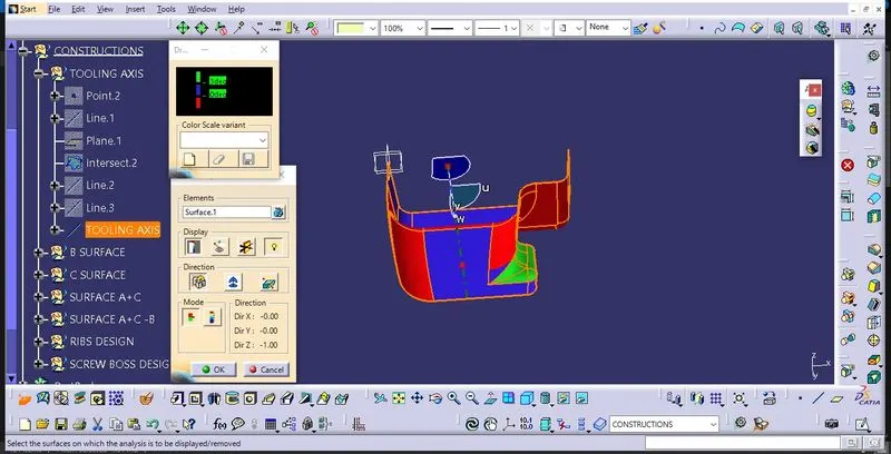
Now perform the draft analysis through the draft analysis toolbar in the bottom. after opening the draft analysis toolbar drag the compass on the tooling axis, click on the lock symbol after compass is aligned.
Step 3: Create class B and class C surface.
Create class B surface by offseting the class A surface by 2.5 mm then fill the boundary of gap if there are any,
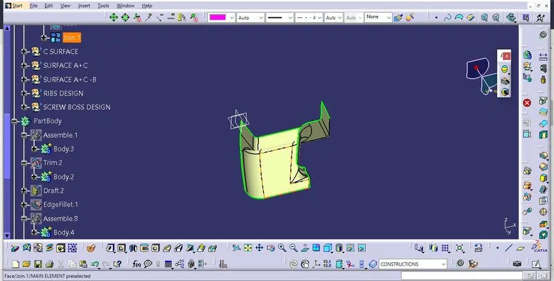
Create Class C surface by using the sweep command, as shown
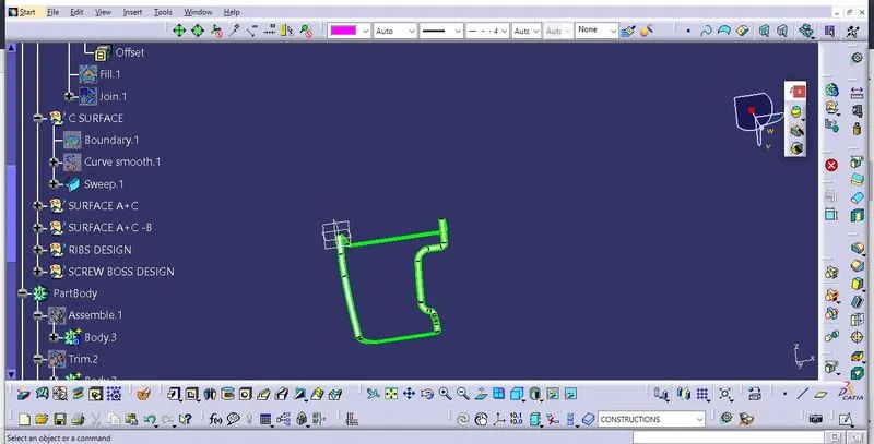
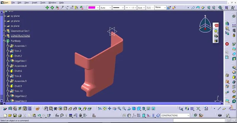
Step 4: Trim Class A and C then finally with the extrapolated B surface. To create the close surface and Now use the close surface command in the part design to create solid model.
Step 5: Create the ribs with the design rules and perform the Rib root thickness analysis as shown below:
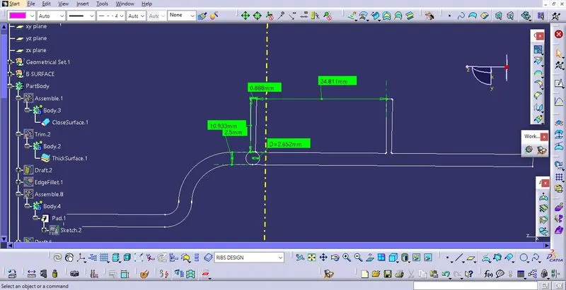
Thickness of wall (t) = 2.5mm
Rib Height = 11 mm approx. (`less than equal to` 5*t)
Rib's tip width = 0.88mm ( >0.75 mm)
Draft on the ribs side = 0.5 deg each
Ribs spacing = 25 mm ( greater than 3*t)
Rib thickness =1 mm (=0.4*t)
Ribs Fillet radius = 0.15 mm ( less than 0.25 mm)
so we can say Ribs are designed with the design rules consideration.
Step 6: Now create the screw Boss with keeping design rules in mind as shown:
Height to diameter ratio= 3:1 ( We have given height = 12 mm and diameter = 4 so ratio= 3:1)
Fillet radius = 0.25 max. ( we have given 0.15 mm)
Draft = 0.5 degrees on walls ( we have given that)
thickness= 40% of nominal wall at base
so we can say our screw boss is designed with design rules.
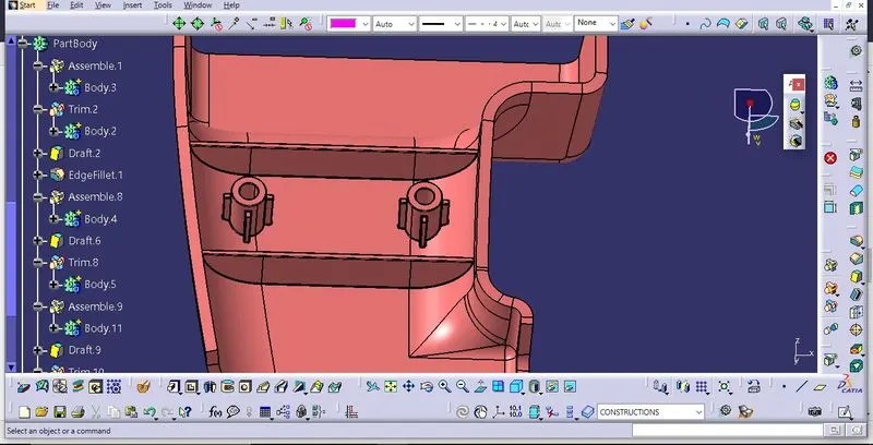
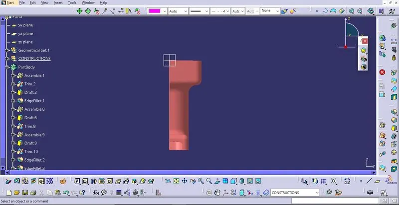
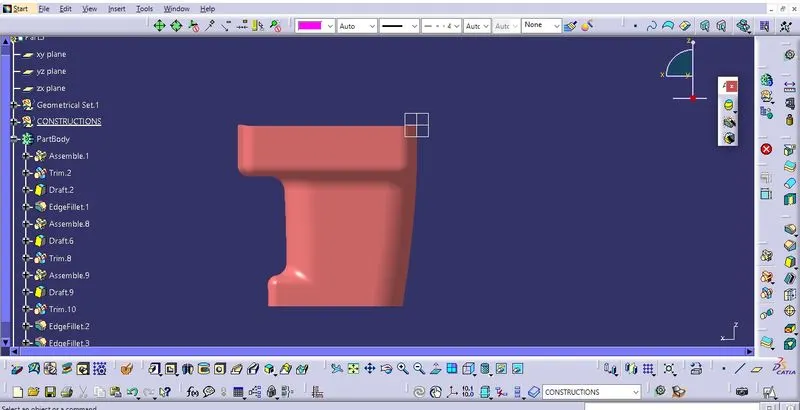
Now perform the draft analysis on created solid model as shown,