Week 9 - Attachment Feature Creation (Ribs & Screw Boss) - Challenge 1
Week 9 - Attachment Feature Creation (Ribs & Screw Boss) - Challenge 1
AIM:- Create the rib for the Drill Handle considering the design rules.
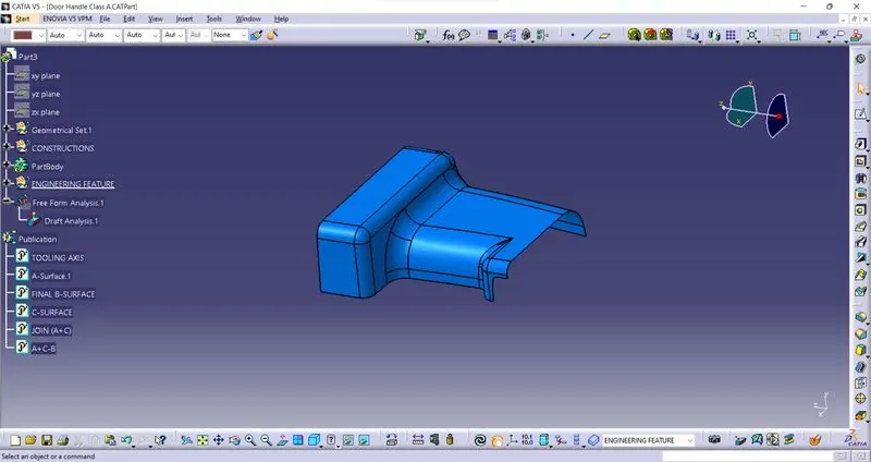
CLASS A-SURFACE-
TOOLING AXIS-
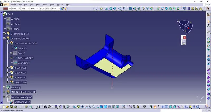
TOOLING AXIS is created by bisecting the axis created on two intersections .the best tooling direction for the class-A surface is along y-axis direction.Flat surface on the center part is extracted for creating the tooling axis in y direction Then created a with the point and direction along y axis.
DRAFT ANALYSIS OF A-SURFACE-
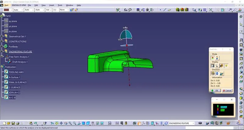
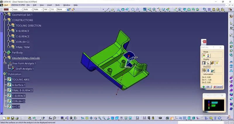
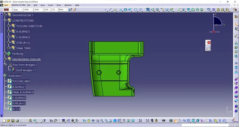
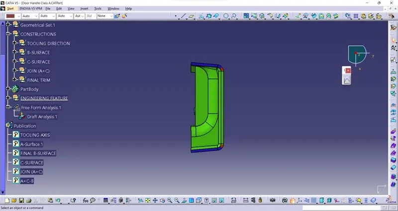
For draft analysis use the compass fucnction to aling the compass to the tooling direction and lock the direction using lock function in the draft analysis tool barthe surface is showing green colour so that the surface clears the minimum draft angle of 0.45 degreeBy using the analyses under the running pointwe can check draft angle on the individual faces. It shows how much draft on specific points when we move the cursor point.
B-SURFACE-
Class B was created by offsetting class A to the thickness of the component, (i.e.) 3 mm. And the improper patches are repaired. the commands used are Multiple Extract, Extrapolate, Trim, Edge Fillet, Surface Fillet, and Join. The Areas where the B-surface has issues are corrected by closing them using commands like Multi section,Sweep,Offset and extract.Finally all the created surfaces are trimmed or joined together with offset surfaces done earlier. This created a single single surface which will act as the final B-surface.
C-SURFACE-
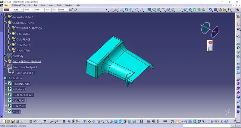
Multiple boundaries are created on the Class A Surface using Multiple Extract Command and a sweep was done with each of the boundaries as a guiding curve and Class A Surface as a reference surface at 90 degrees. Those sweeps are then joined with the Class A Surface to form C Surface.
JOIN (A+C) & TRIM B-SURFACE-
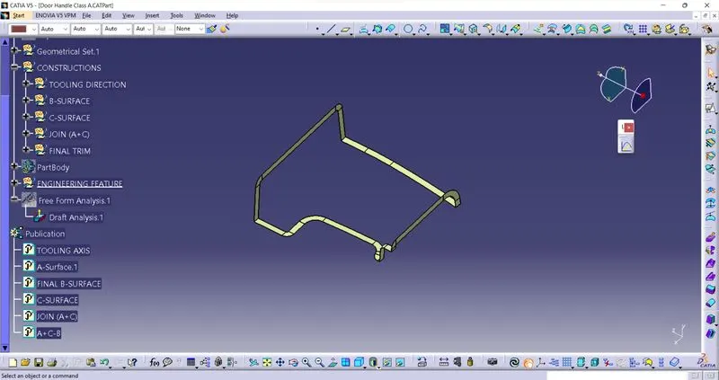
All the surfaces (A+C) are joined together and trim the B surface to form a closed body.
Boundary is selected and the body is picked. Since an error popped up it can be understood that all surfaces are joined with each other to form a proper closed surface body.
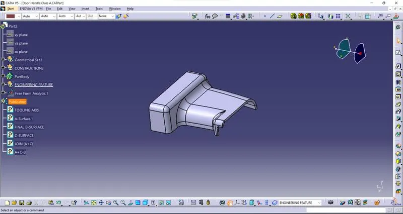
Finally in part design workbench, using close volume it is changed to a solid body.
FOR CREATING THE SOLID BODY I'LL HAVE TO CHECK THE BODY IS CLOSED OR NOT.
SOLID BODY-
ENGEERING FEATURE-
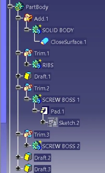
SKETCHES FOR CREATES THE RIBS AND SCREW BOSSES-
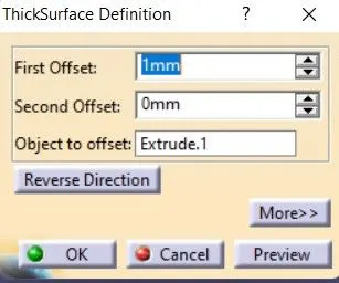
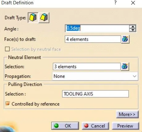
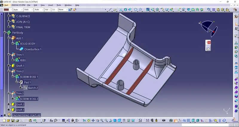
RIBS-
SCREW BOSSES-
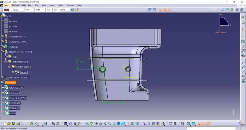
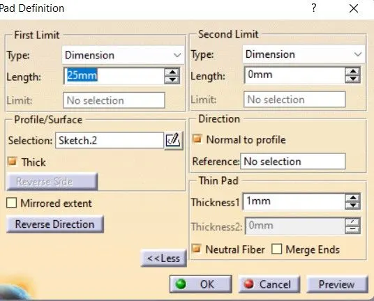
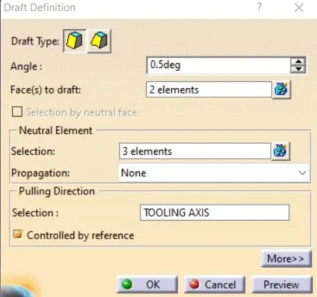
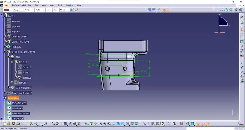
MADE ONE AND THEN TRASNFER COMMAND USE TO CREATE SECOND SCREW BOSS.
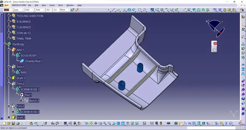
DRAFT ANALYSIS-
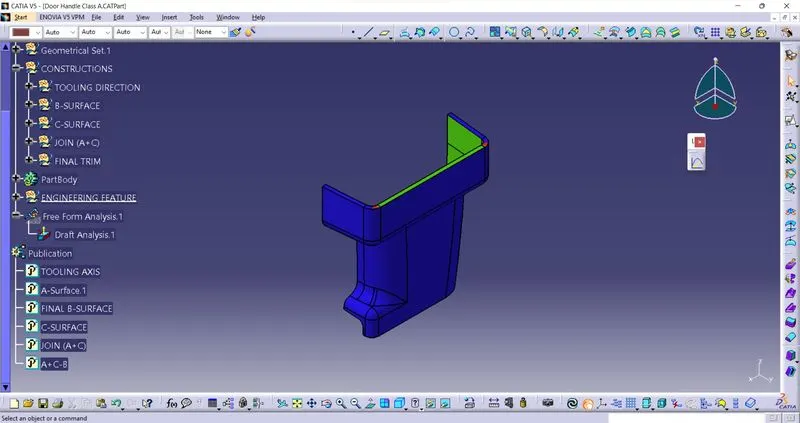
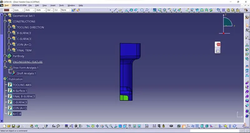
Draft analysis is done using featured draft analysis tool Use the compass fucnction to aling the compass to the tooling direction and lock the direction using lock function in the draft analysis tool bar the surface is showing green colour so that the surface clears the minimum draft angle of 0.45 degreeBy using the analyses under the running pointwe can check draft angle on the individual faces. It shows how much draft on specific points when we move the cursor point.
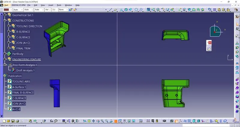
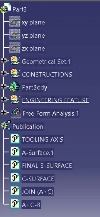
GEOMETRICAL TREE STRUCTURE WITH PUBLICATION-
PART BODY TREE STRUCTURE-
ISOMETRIC VIEW-
FRONT VIEW-
SIDE VIEW-
TOP VIEW-
ALL VIEW IN ONE FRAME-