Week 9 - Attachment Feature Creation (Ribs & Screw Boss) - Challenge 1
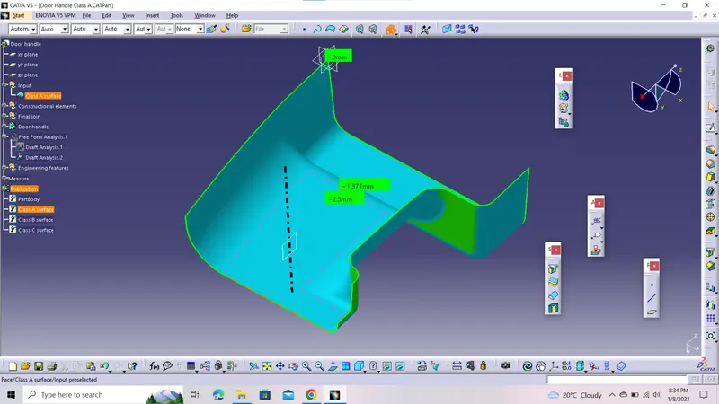
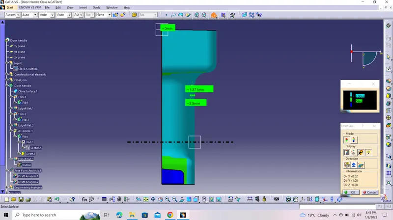
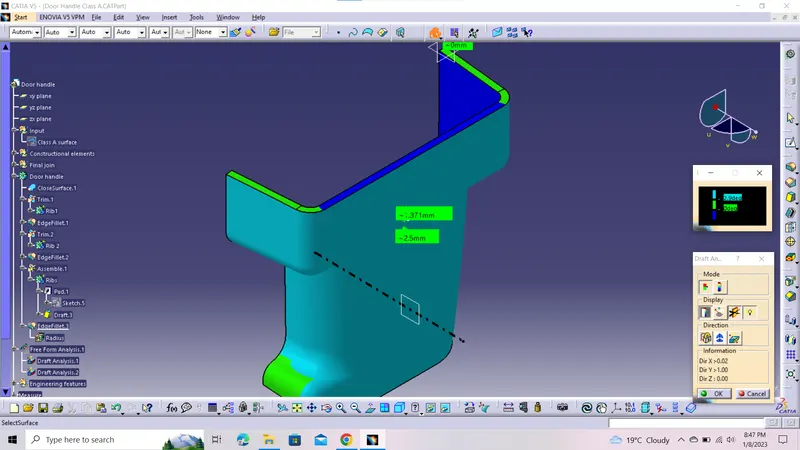
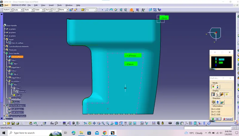
Creation of solid model of Door handle by using Class A surface and also adding engineering features like ribs and screw boss to door handle and also to perform draft analysis on class A and final component.
Door handle:A Door Handle is built to detach the door latch to enable the door's opening.
Important terminologies:
- Ribs: They are thin extensions that run perpendicular from a wall or plane. They are commonly used to provide additional support and strength to a part. Thickness and location are essential to rib design.
- Screw boss: Bosses are projections designed to accept inserts, self-tapping screws, etc. for use in mounting, fastening or assembling parts.
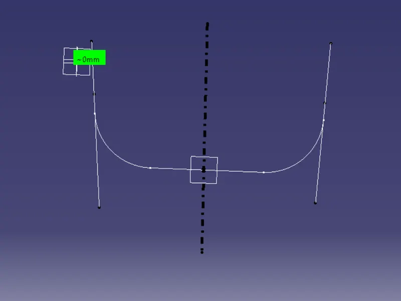
1)Steps to be followed to create tooling axis:
- Initially, confirm the surface through which the tooling axis to be passed and extract the surface.
- Create a point on the surface and offset a plane on that point and make an intersection of class A surface using offseted plane.
- Make 2 lines about the 2 walls and make a bisector and the bisector itself is the tooling axis.
2)Steps to create class B surface:
- Offset the class A surface to distance of 2.5mm inwards .
- Make sure that there is no incomplete patches within the surface .
3)Steps to create class C surface:
- Create the boundary all along the edges of the class A surface.
- Using sweep command, create surface along the boundary along class A surface.
4)Initially, join the Class A and CLAss C surface and trim with Class B surface.
5)Changing to part design work bench, craeate the soild pf Door handle using its suface model.
6)Steps used to create ribs:
- Extract the surface , on which ribs to be designed and make a sketch on it.
- Extrude to appropriate height as per design rules.
- Thicken it as per design rules and provide draft angle of 0.5degree.
- Unitrim it to solid door handle and fillet the rib of 0.25mm radii.
- Reapeat the similar procedure to create the 2nd rib at distance more than 6mm.
7)Steps to create screw boss:
- Create a sketch on extracted surface on body and make a sketch of concentric circles as per design rules.
- Extrude it to a distance as per design rules.
- As per design rules, follow it.
- Add it to the main body.
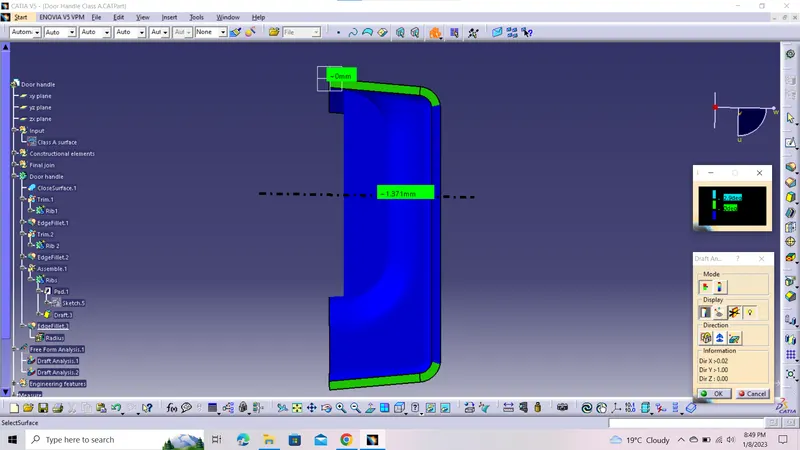
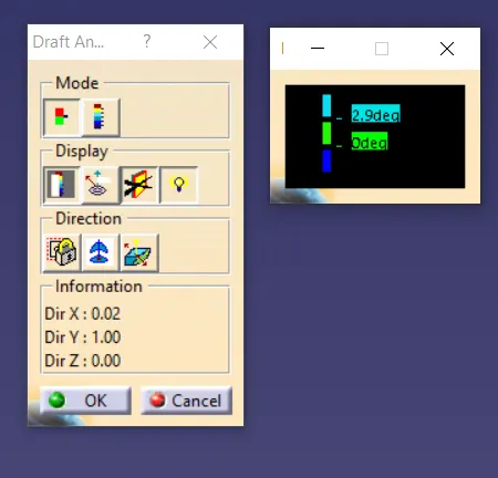
8)Steps to do draft analysis on class A surface and final out product:
- ON the draft anlaysis and change the material mode.
- Place the coordinate system on the tooling axis.
- Select the component that needed to be analysed.
- Repeat the similar steps to perform the Draft analysis to class A surface.
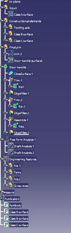
9) Publish Tooling axis, Class A , Class B , Class C surfaces for ease of accesible.