Week 9 - Attachment Feature Creation (Ribs & Screw Boss) - Challenge 1
DOOR HANDLE
AIM:
- To Create the Door Handle Component from the given Class-A surface.
- To Create the tooling axis for the given Class-A Surface meeting the requirements of the draft angle.
- To Attach B side Features in the component.
- To perform the Draft analysis on the model.
Considered Thickness of the component to be 2.5 mm
INTRODUCTION:
CLASS-A SURFACE: A surface made by the designer which is given as input to the plastic modeler to work on. It is an aesthetic surface
and the outermost surface.
CLASS-B SURFACE: A surface below a certain thickness from the class-A surface is a class-B surface. This is the surface that contains
engineering aspects of a model.
CLASS-C SURFACE: A surface that joins class-A and class-B surfaces is a class-C surface
Attachment Feature Creation (Ribs & Screw Boss)
Methodology and Tools Used :
In this design we will focus on the following steps
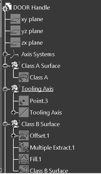
- Tooling Axis
- Draft Analysis
- Class B Surface
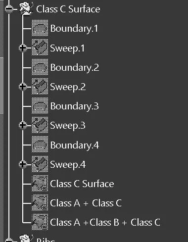
- Class C Surface
- Making a solid model from FINAL TRIM ( Class A + Class B + Class C ) surface
Following tools were used to reach the final Solid Model :
- Extract
- Un - trim
- Trim
- Offset
- Extrapolate
- Boundary
- Edge Fillet
- Sweep
- Join
- Close Surface ( Part Design )
- Attachment Feature Creation (Ribs & Screw Boss)
TOOLING AXIS
Tooling Axis for Plastic Part :
Tooling direction is main consideration for plastic part and mold parts because it defines movement of mold part and possibility of plastic part to come-out from mold part (Core and Cavity).
- In Molding machine arrangement is given to open the mold along a direction which is known as Tooling Direction.
- In other words. The mold is built from two separate halves (Core and Cavity) and tooling direction basically define the direction of mold pulls apart.
- Tooling direction is known as primary direction.
There are two methods to create Tooling Axis -
- Bisecting method &
- Inertia method
Bisecting method-
- By taking Extract of the base and creating a point on centre of the extact and then creating axis system or plane on that point .
- Intersecting the Class A with the point .
- Creating bisecting line using the extracts on the intersection .
- Checking the tooling axis created is clearing all the sides of the Class A by keeping it in Normal view mode.
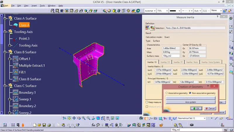
Inertia Method
In this given Door Handle Class A surface the tooling axis is created using inertia method as shown in the fig below -
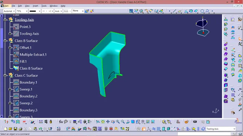
FOR CLASS B SURFACE :
- Invisible Surfaces.
- Surface mostly don't have textures
- Surface needs to be created according to the class-A surface.
- Having all features in B-side surface only.
- Surfaces which is having TANGENT CONTINUITY IS CALLED class-B
Just Offseted the Class A for 3 mm & performed some modifications as per requirement
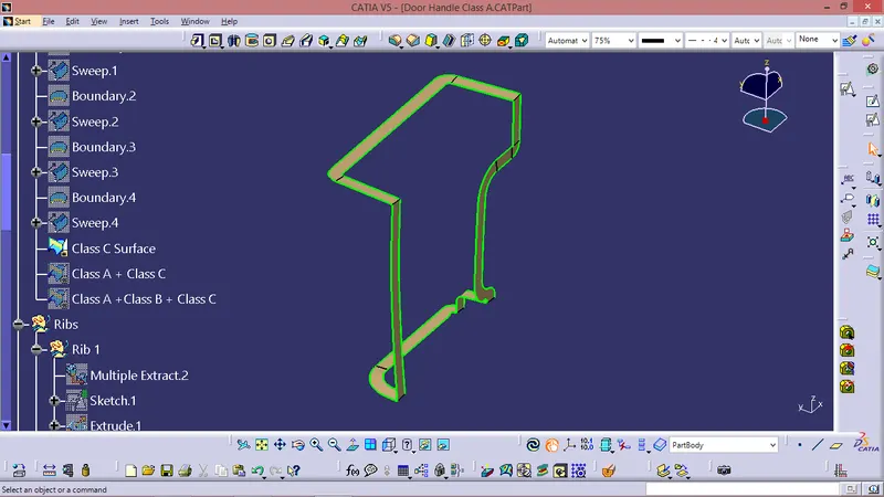
FOR CLASS C SURFACE:
Took boundries for class A in some sections and in other sections took Multiple extract for Class A Surface.
Sweept using boundries and Multiple Extract with Reference surface.
CLASS A CLASS C TRIM
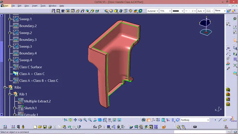
Final Trim -
Class A + Class B + Class C
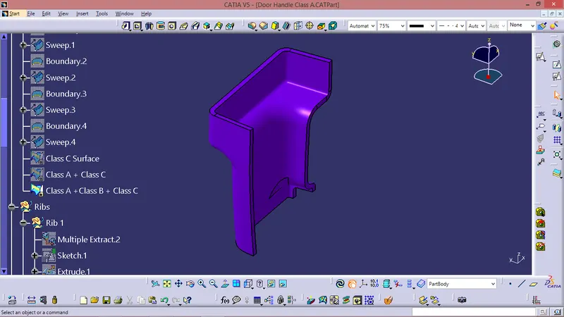
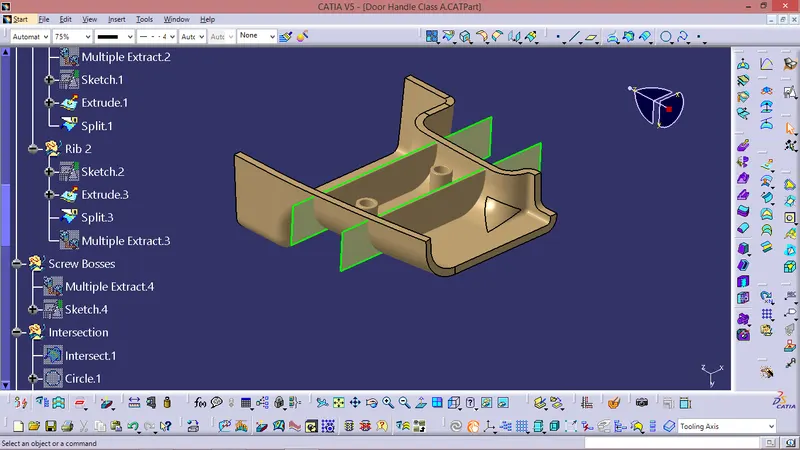
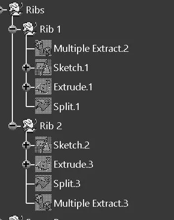
For Creating RIBs -
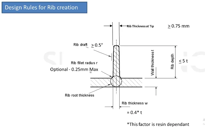
- Design Rules for Rib Creation
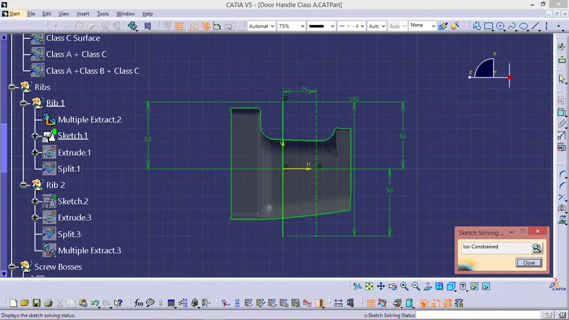
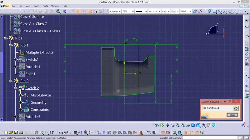
SKETCH
Calculations
1.
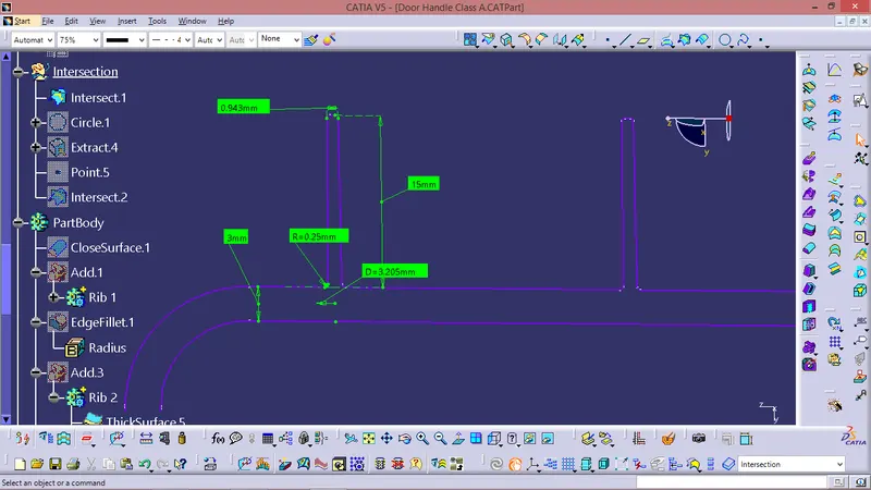
To find the height of the Ribs , h=Wall thickness * 5
=3 * 5
= 15 mm
Therefore, the height is 15 mm
2.
The thickness of the Ribs is -
Thickness , w = 0.4 * t
= 0.4 * 3
= 1.2 mm
Therefore , the thickness of the rib is 1.2 mm
3. The draft is applied to the sides of the ribs. As per the design rule, the ideal draft angle is 0.5 deg
4. Then fillet is applied to the faces of the rib. As per the design rule, the fillet can be 0.25 mm.
5.
Now, For checking the Rib root thickness.
To check for the Rib root thickness, We have to take an Intersection with the XY plane and the Coin holder component. Once we get to the intersection we have to create a tri-tangent circle at the rib area and measure it. The value must be within 30% greater of the wall thickness.
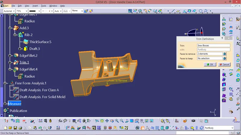
For Creating SCREW BOSS
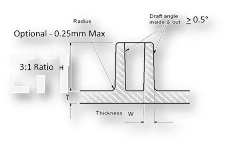
Screw Boss features are commonly found in injection molding designs. They are used to aid in the assembly of molded parts by providing a channel for a screw. Their primary use is to strengthen holes or slots in the surface present in the part model.
Design rules consider while creating a screw boss
• Thickness
• Draft
• optional radii
• Boss gussets
• Type of ejection
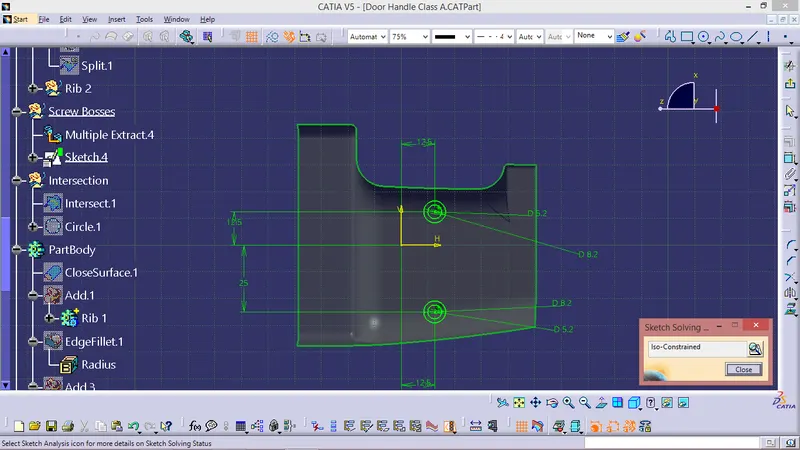
The construction process of creating the screw boss is explained below:
For thickness, the design rule is as follows,
Thickness,w=0.6*T
=0.6*3
=1.8 mm
Therefore, the thickness of the boss can be 1.8 mm per side.
In this case, we have considered the size of the screw boss as M06.
Then fillet is applied to the faces of the rib. As per the design rule, the fillet can be 0.25 mm.
Sketch
DRAFT ANALYSIS :
- Class A surface draft analysis -
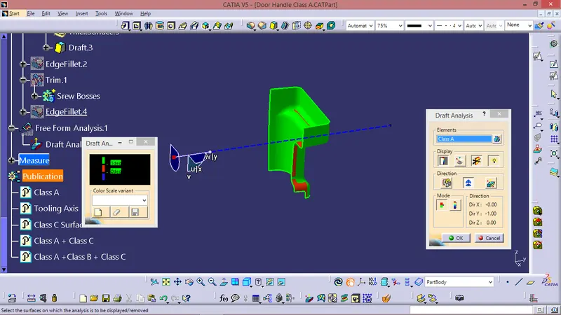
The above image shows the draft analysis in which green color surfaces shows that they are having an angle of more than 3 degrees but the surface in red color shows it is less than 3 degree. These are the results of the draft analysis which are very crucial for determining the feasibility of the product
Solid component draft analysis :
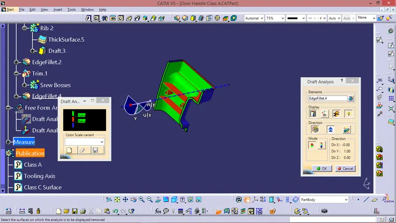
The draft analysis command enables you to detect if the part you drafted will be easily removed. This type of analysis is performed based on colour range identifying zones on the analysed element where the deviation from the draft direction at any point, corresponds to specified values. After draft analysis done we can observe that the green colour shows that the drafted walls of the switch bezel are above 3 degrees which is a permissible criteria to manufacture in injection moulding.
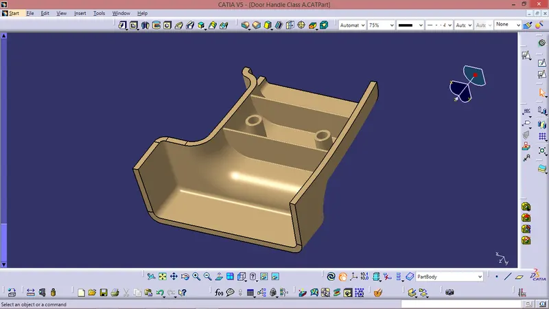
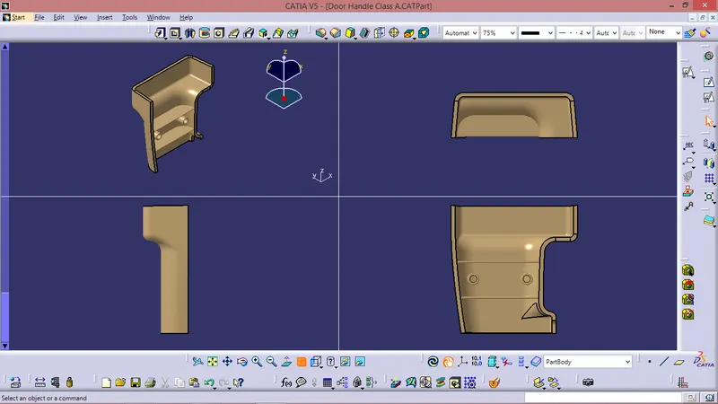
SOLID MOULD :
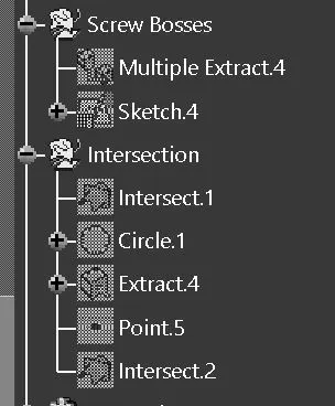
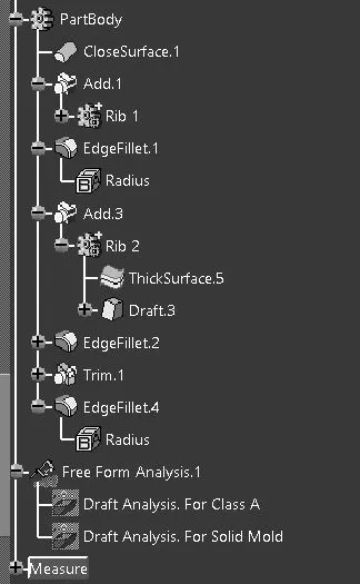
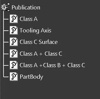
TREE STRUCTURE :
CONCLUSION:
- The Tooling axis and the SolidCAT part with B Side Features is created from the given Class A Surface and Draft Analysis is Performed.