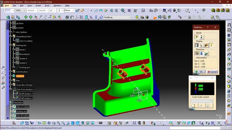
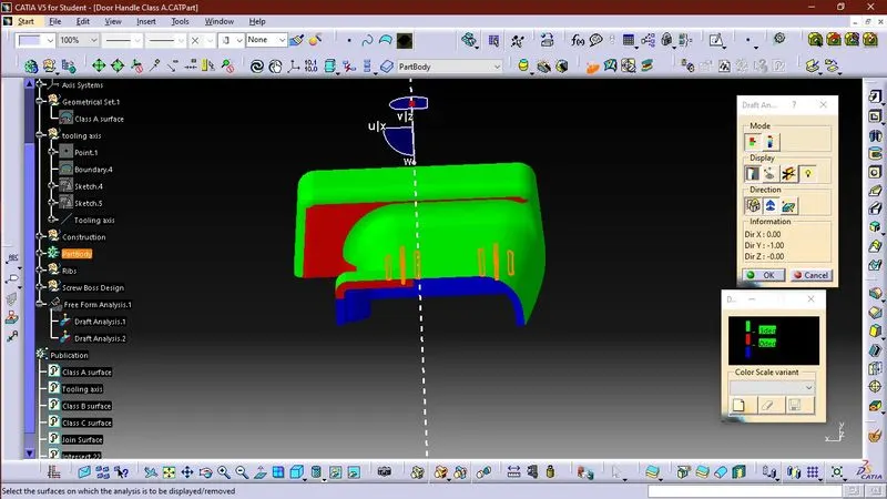
Week 9 - Attachment Feature Creation (Ribs & Screw Boss) - Challenge 1
Attachment Feature Creation
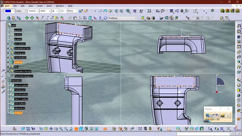
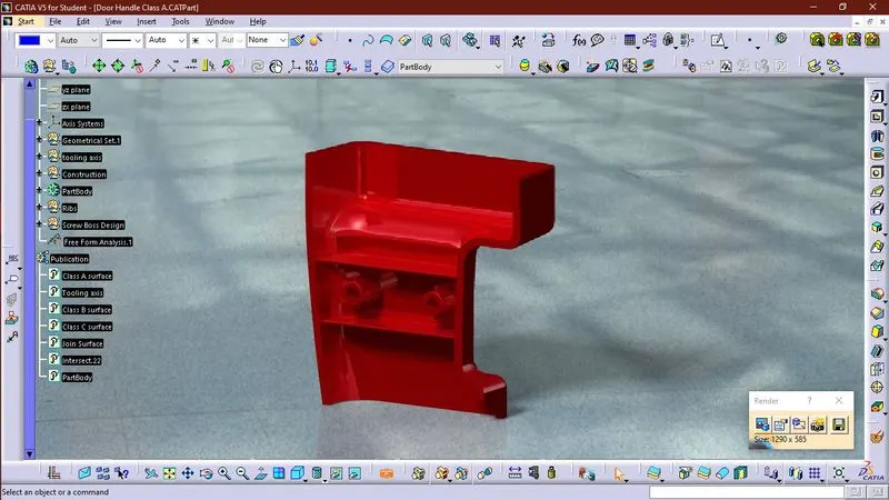
Following is the image of the part file on which we have to create attachment features.
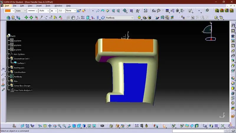
As the part file is a class A surface, therefore, we first have to create a solid part with the help of Class A. Assuming thickness for the part as 3 mm.
First, we create a tooling axis for it by using the intersection method.
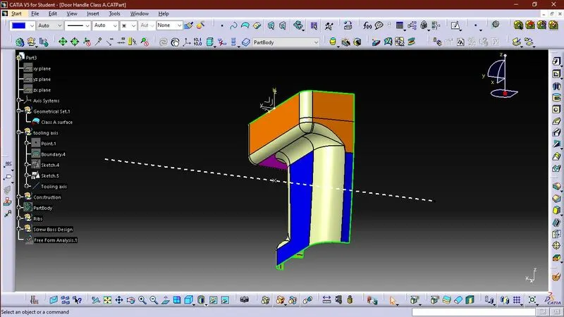
Then we run a draft analysis on class A surface.
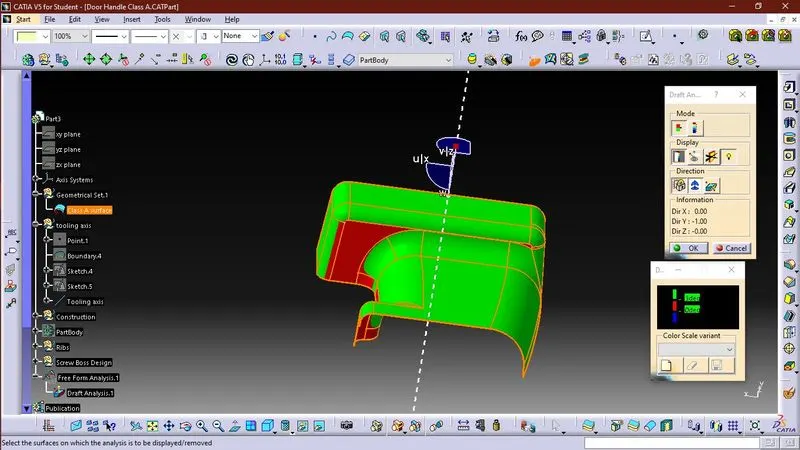
Now we created a Class B surface by using the following tools:-
1. Extract
2. Disassemble
3. Untrim
4. Extrapolate
5. Trim
6. Split
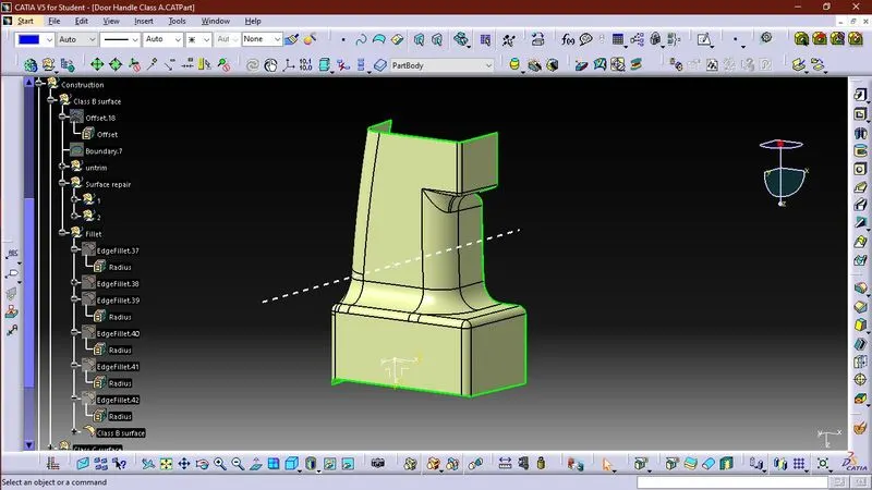
Then we created a Class C surface by using the sweep tool
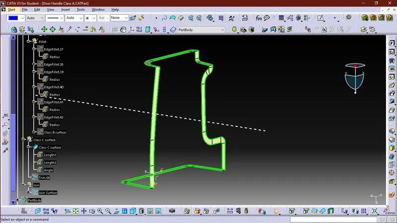
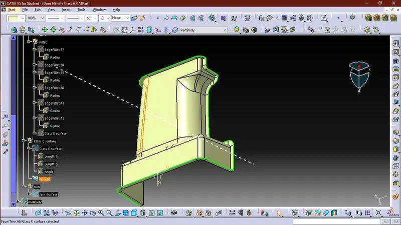
Then we joined Class A, Class B, and Class C surfaces
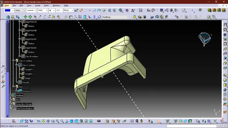
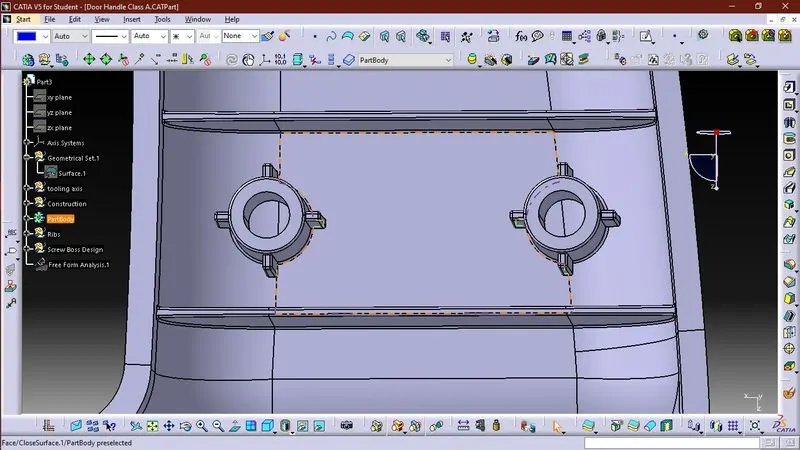
Then we convert our final join into solid part by using Close tool
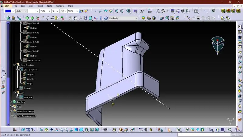
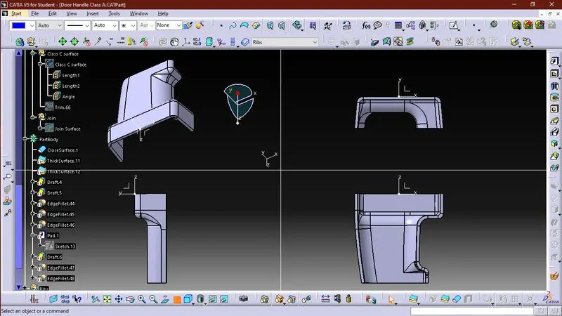
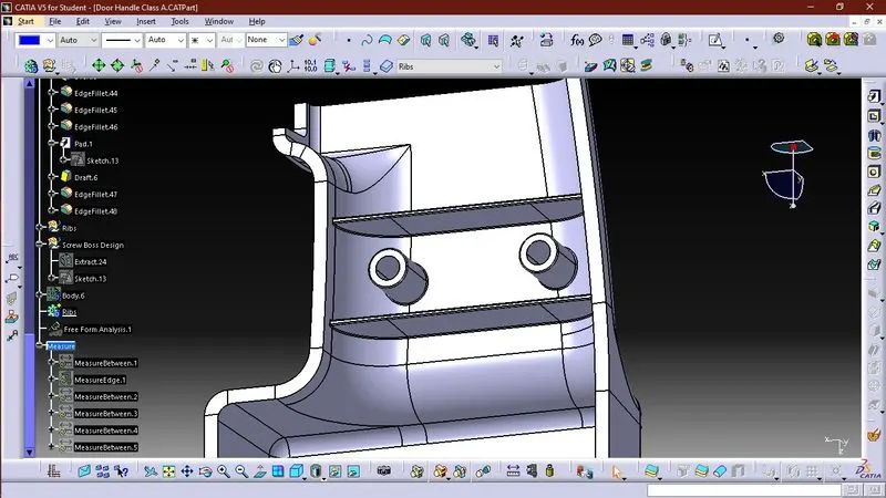
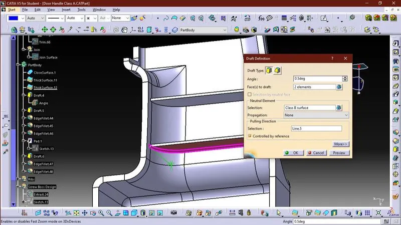
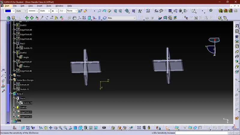
1. Create the rib for the Drill Handle considering the design rules mentioned in the video.
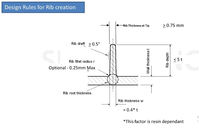
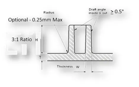
Design limit for Ribs
| For 3 mm Thickness | Max Rib Thickness at base @ 40% (mm) | Min Rib Thickness at Tip (mm) | Min Draft (degree) | Max Rib Height (mm) | Distance between Two ribs (heigth/distance <3 mm) | ||||
| Ideal | 1.2 | 0.75 | 0.5 | 25 | - | ||||
| Our part | 1.196 | 0.972 | 0.5 | 13.5 | 20.804 |
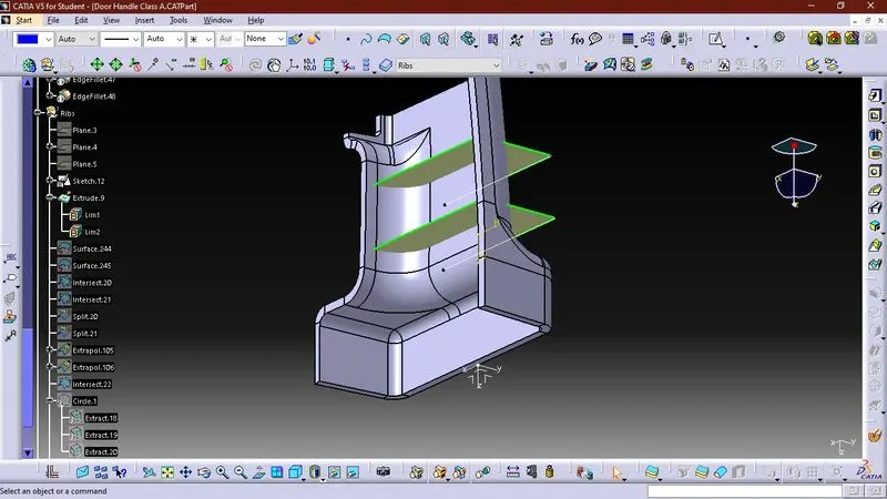
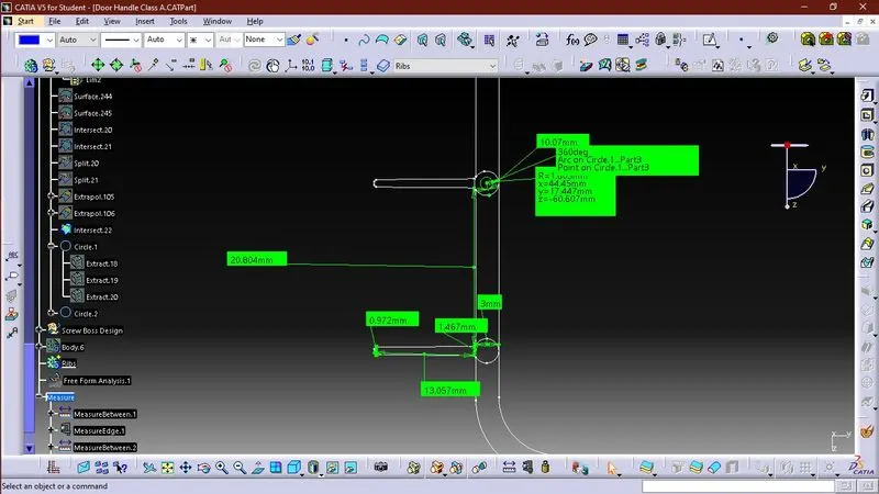
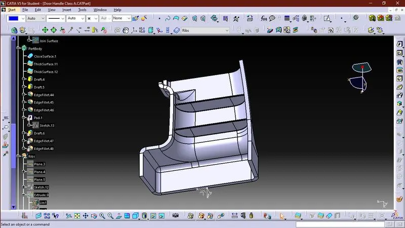
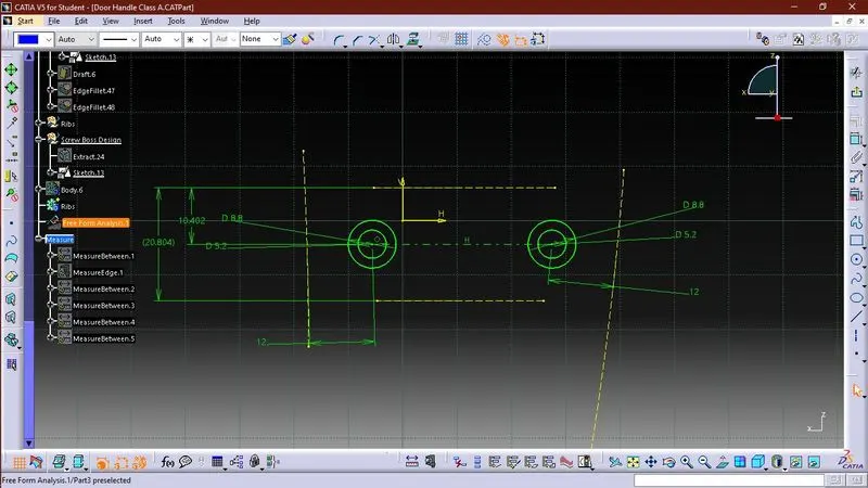
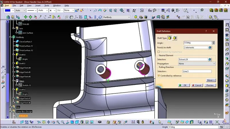
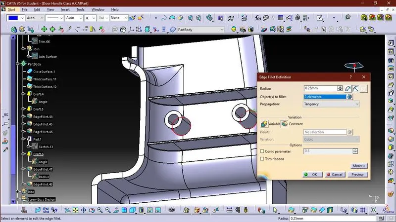
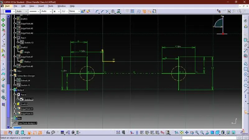
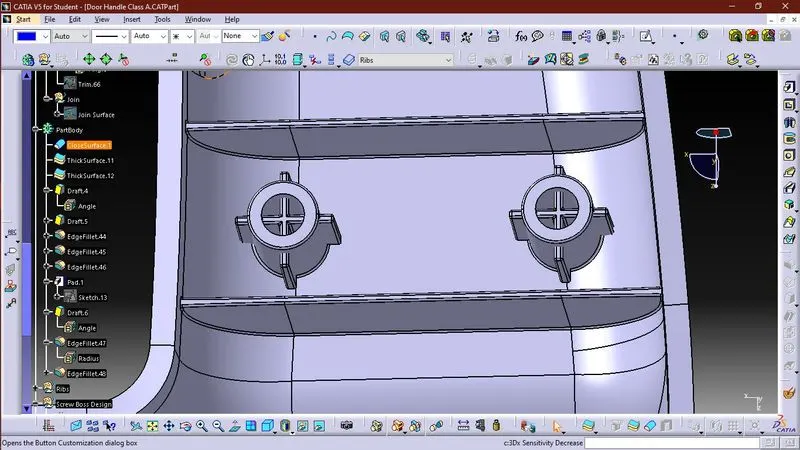
2. Create the Screw boss for the Drill Handle considering the design rules mentioned in the video.
General Guidelines for Bosses:
- Draft - 0.5 degrees on the walls of boss
- Thickness - Typically 40%* of the nominal wall at the base.
- Height to Diameter Ratio - 3:1
- Radii - 0.25mm maximum radii.