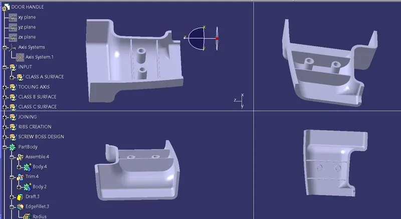
Week 9 - Attachment Feature Creation (Ribs & Screw Boss) - Challenge 1
OBJECTIVE
Design of ribs and screw boss for Drill Handle following the design rules.
PROCEDURE
- Creation of Tooling Axis
- Creation of CLASS B Surface
- Creation of CLASS C Surface
- Creation of Ribs And Screw boss
- Perform draft analysis
CREATION OF TOOLING AXIS
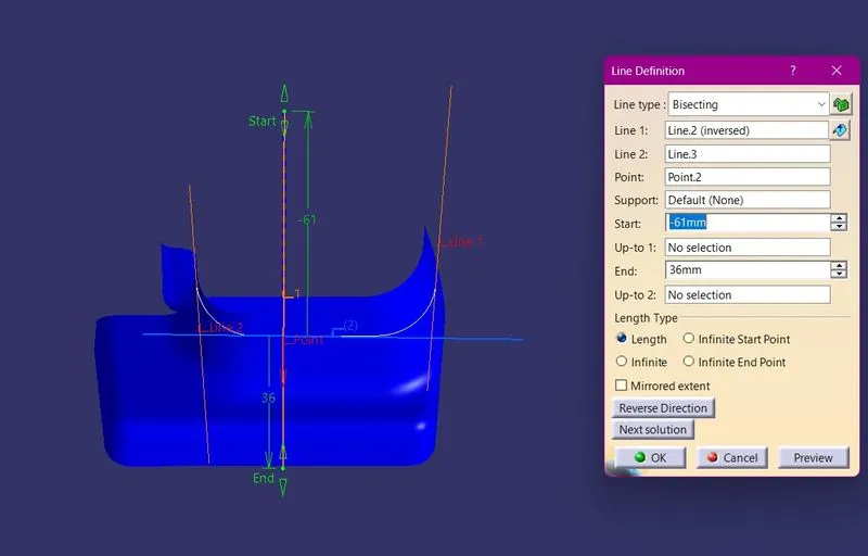
Tooling axis is the direction in which the mold and cavity opens and closes in the injection molding operation.
1- We have extracted a face of class A surface and created a point on it.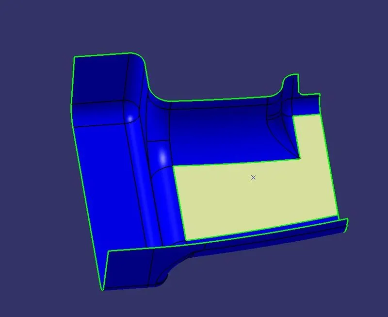
2- We created an intersection line of the part and created two lines by using the intersection line
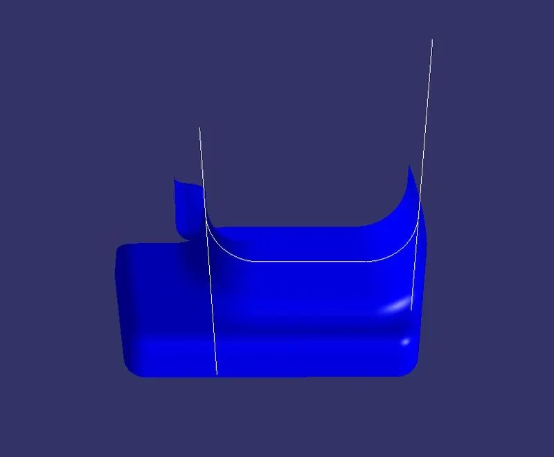
3- We have created a bisecting line using those two lines and the middle point. That bisecting line is the tooling axis for this part.
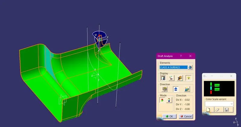
DRAFT ANALYSIS OF CLASS A SURFACE
Draft analysis is done to know wheather the part will be easily manufacturable by the given draft angle or not. It will ensure that the part will not stuck in the core and cavity.
PROCEDURE TO PERFORM DRAFT ANALYSIS:-
- Right Click on Tab < Go to Analysis < Feature Draft analysis
- Put the View Mode in material option
- Align the compass with the tooling direction line
- The surface will turn into green colour it means the part is manufacturable with the given draft angle.
We have given minimum 3deg. draft and the green colour parts are easily removed from the mold.
CREATION OF CLASS B SURFACE
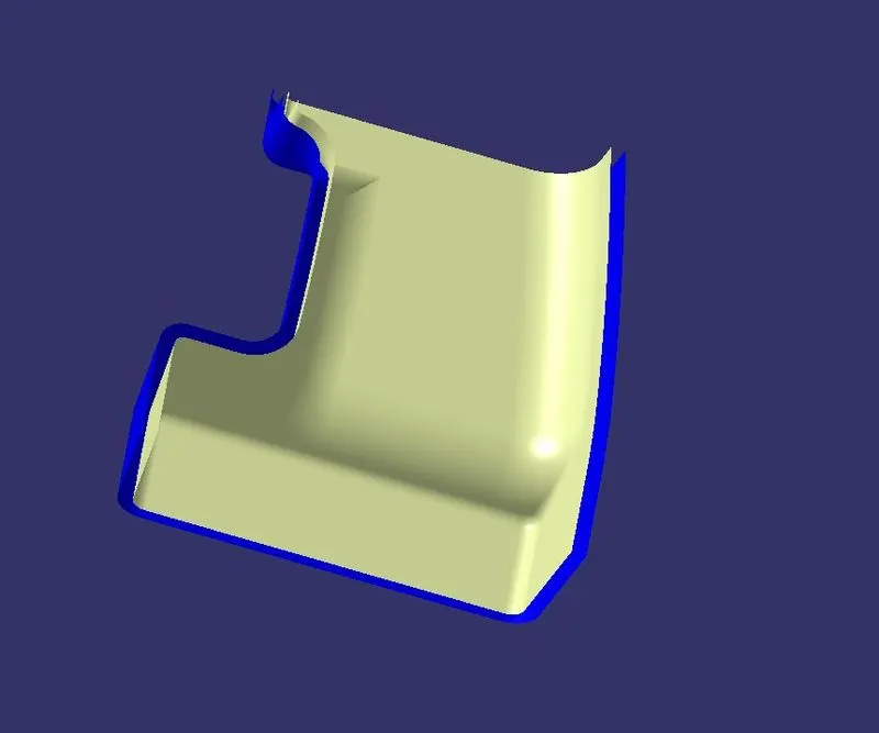
Class B surface is used for Engineering purpose. All the design parameter are done on the Class B surface. We have offsetted the class surface for 3mm to created CLASS B Surface.
CREATION OF CLASS C SURFACE
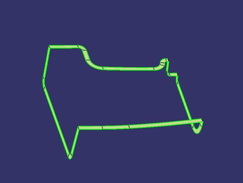
Class C surface is used to join the Class A and Class B surface together. For this surface Customer feels do not need to meet a high cosmetic finish.
SOLID SURFACE
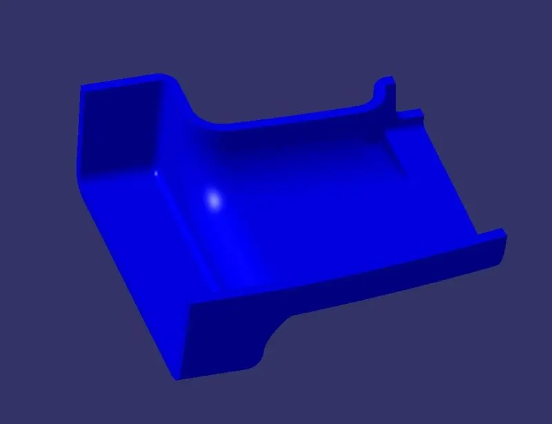
We have joined the CLASS A-B-C together and make a closed solid surface.
CREATION OF RIBS
Ribs provide a means to economical stiffnes and strength in molded part without increasing extra wall thickness. They also facilitate locating and arresting components of an assembly and provide alignment to the mating part.
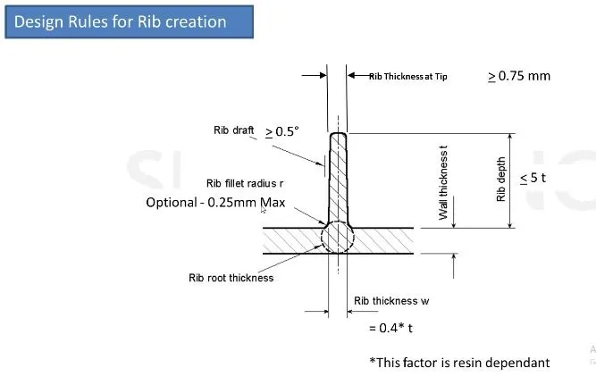
1- We have created sketch for the ribs
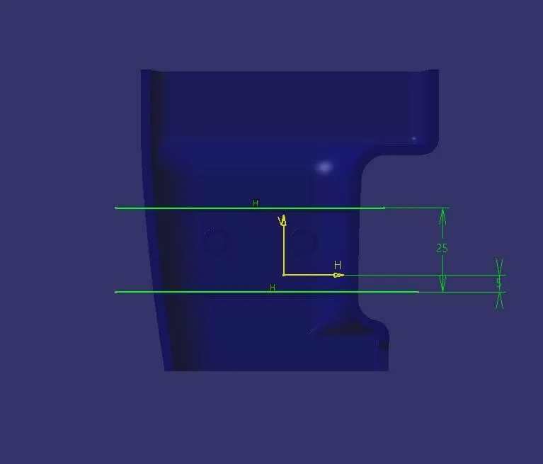
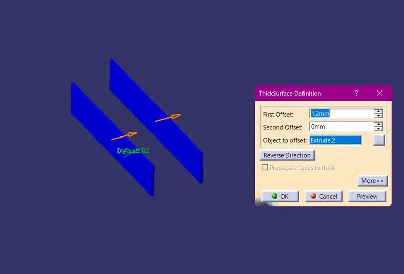
2- We have extruded those sketch and made it a thick surface. We have given it 1.2 mm thickness as per the design rule of 0.4*part thickness= Ribs thickness
3- We have given the height of the ribs is 15mm as per the design rule, Ribs depth = 5 * Part thickness
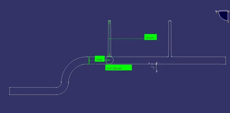
4- We have provided fillets of 0.25mm radius.
CREATION OF SCREW BOSS
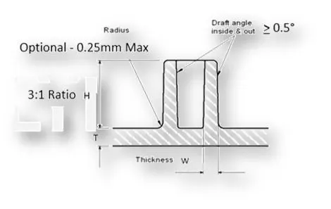
General Guidelines for Bosses:
- Draft - 0.5 degrees on the walls of boss
- Thickness - Typically 40%* of the nominal wall at the base.
- Height to Diameter Ratio - 3:1
- Radii - 0.25mm maximum radii.
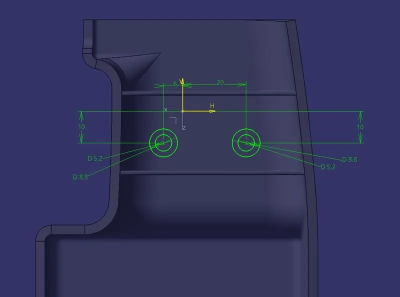
1- We have created sketch for the screw boss. Inner diameter we have given as per the M6 screw is 5.2 mm and outer diameter is 8.8mm
part thickness * 0.6= One side wall
3*0.6= 1.8mm, both side = 1.8*2= 3.6mm
Outer diameter = inner diameter + both side wall
5.2+3.6= 8.8mm
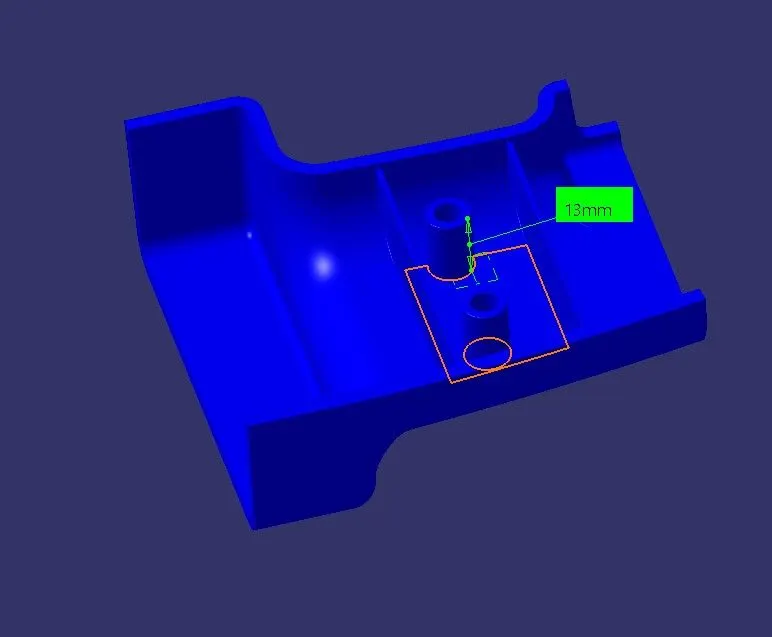
2- We have pad it to the height of 13mm
DRAFT ANALYSIS OF FINAL PART
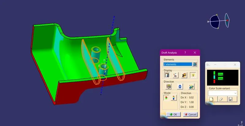
Some part are showing red because of the ClASS A surface defects so we have to inform the CLASS A surface designer team to rectify those regions as per the tooling direction.
FINAL IMAGE