Week 9 - Attachment Feature Creation (Ribs & Screw Boss) - Challenge 1
Creating rib and screw boss with the given class-A surface:
To create ribs and screw bosses first we need to convert the given class-A surface into a closed body. A closed body is created by class-B and class-C surfaces.
Given class-A surface.
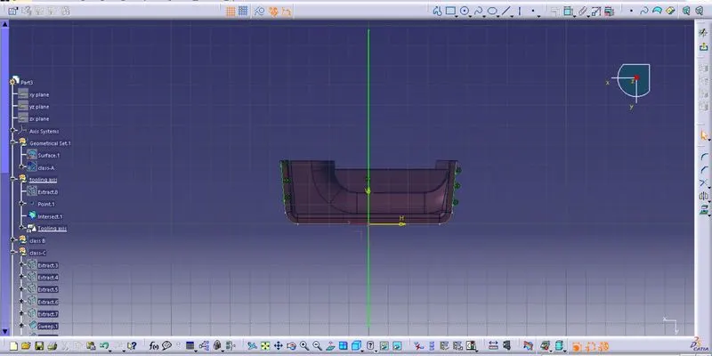
First, we need to check the draft analysis of the given class-A surface. To do so, we need to create a tooling axis. The tooling axis is created by selecting the bottom face, extracting it, and placing a reference point and an axis system. Get the intersect curve of the class-A surface using the axis system. once we get the intersect curve, draw two lines on the intersect curve. use bisecting line option and select the two lines. Using the two lines and bisecting method we get the tooling axis. The sketch is shown in the below image.
Draft analysis of the class-A surface with a minimum draft angle of 3deg.
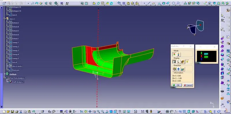
The red colour region indicates the surface has a lesser draft angle i,e. less than 3deg. So the class-A surface needs to be modified to improve the red colour region.
Creation of class-B surface.
To create the class-B surface, we use extract, join, offset and multisection solid commands. Extract the surface of the class-A that is divided into smaller patches, join the and offset them to a distance of 2.5 or 3mm. if there are some patches that are not offset, use a multisection surface to fill the gaps. The created class-B surface is shown in the below image.
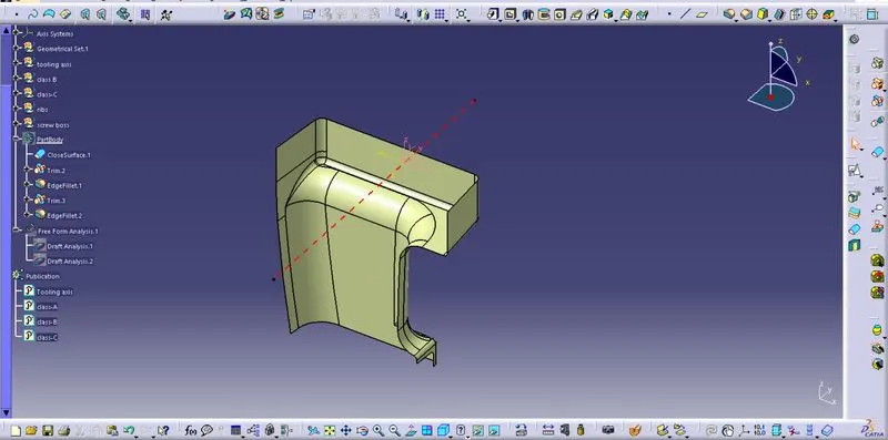
Creation of clas-C surface:
To fill the area between class-A and class-B surfaces we need to create the class-C surface. To create a class-C surface we need to extract the boundary of the class-A surface and use the sweep command to generate the class-C surface. The class-C surface is shown below.
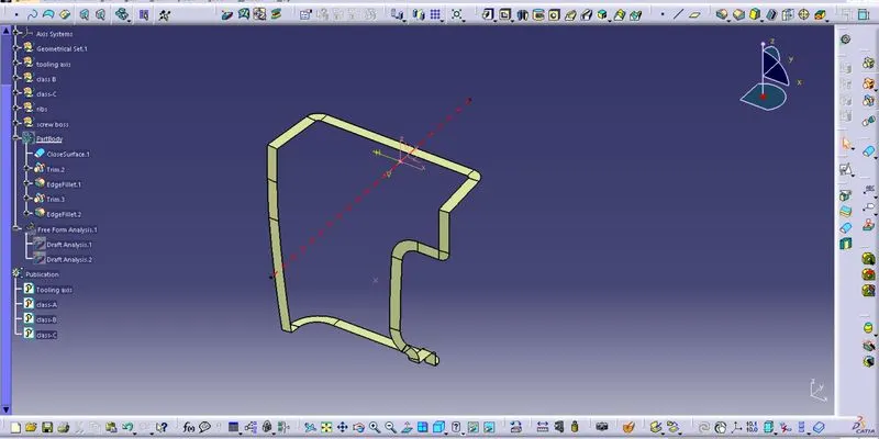
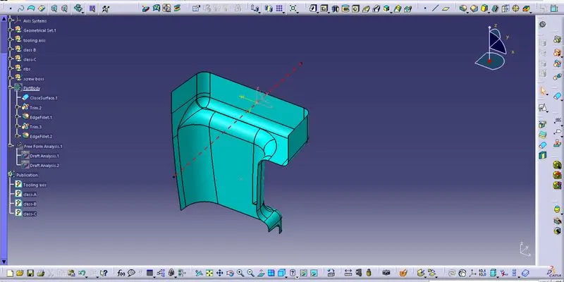
After creating the class-C surface we trim it with the class-B surface. The joined class-B and class-C surface is shown below.
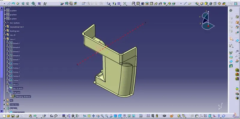
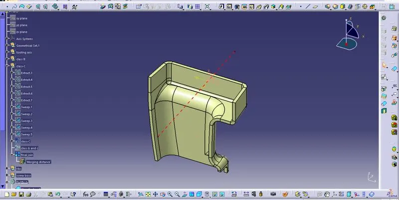
At last, we join class-A surface with this class-B and class-C trim. Getting a thickened component of 3mm.
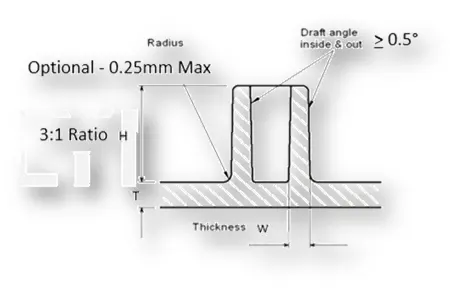
After creating the closed body now we need to attach the ribs and boss to the component. Both the rib and boss have certain design regulations. They are shown in the below images.
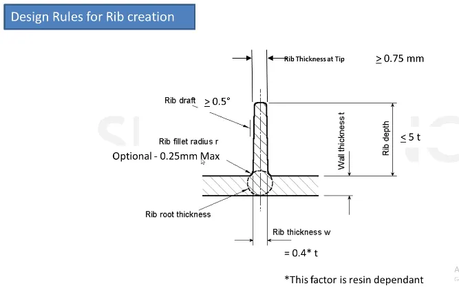
To create ribs, first, we need to extract the face on which we want to place the rib. It should be the Class-B surface because all the ribs, boss are B-side features. On the extracted face place a reference point and using the reference point we do the position sketch. The Thickness of the component is 3mm and as per the design regulations we created a sketch. It is shown in the below image.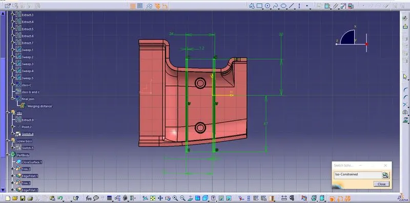
Once we drew the sketch, we get into the part workbench and use the pad feature. After we create the pad, we provide the draft angle of 0.5deg with the tooling axis as the pulling direction. This gives the walls of the rib a draft of 0.5deg. To add this rib to the main body we use the union trim option and select the faces that are to be removed. Once the ribs are added to the main body, provide the fillets of 0.25mm to all the edges of the rib.
To create the screw boss, we perform similar operations that are used for rib. Extract a face of class-B, insert a point and use positioned sketch to draw the required sketch for the boss. The screw boss sketch is drawn by following the design considerations of wall thickness, height, draft angle and fillet radius. The image of the boss sketch is shown below.
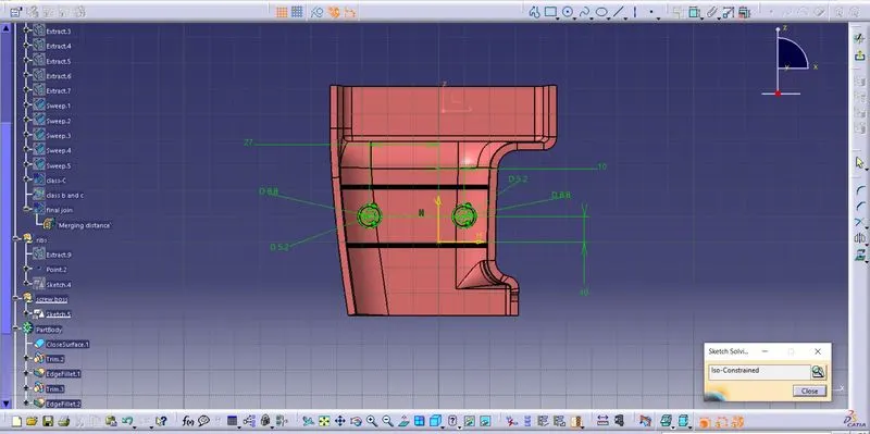 '
'
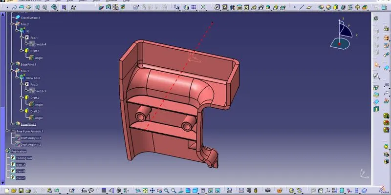
Once we drew the sketch, we get into the part workbench and use the pad feature. After we create the pad, we provide the draft angle of 0.5deg with the tooling axis as the pulling direction on both the inner walls and the outer walls. To add this boss to the main body we use the union trim option and select the faces that are to be removed. Once the screw boss is added to the main body, provide the fillets of 0.25mm to all the edges of the boss.
Draft analysis of the final component:
As we provided the draft angle for the rib and screw boss as 0.5 deg, we perform the draft analysis with 0.5deg.
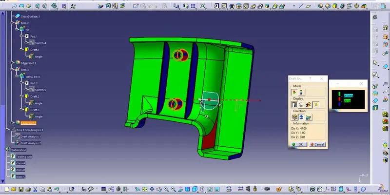
With a 0.5deg draft angle, there are certain regions which have a blue colour and red colour regions. When the draft angle is changed to 0.45 deg the red colour region has been removed but the blue region is not getting solved.
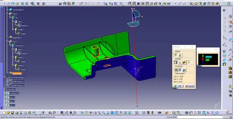
So, if the class-A surface gets modified, then all these blue and red colour regions can be solved into green.
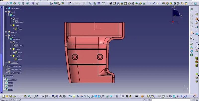
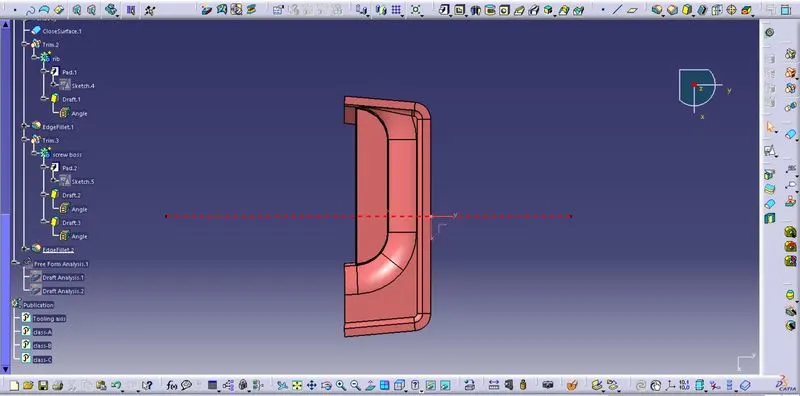
- Screenshots of the completed design in various orientations (Isometric, Front, Side, and Top View).