Attachment Feature Creation (Ribs & Screw Boss)
ATTACHMENT FEATURES CREATION
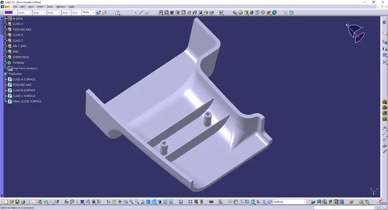
OBJECTIVE: Create Rib and Screw boss for the door handle considering design rules using Class A surface of door handle with the thickness of the component 2.5 mm.
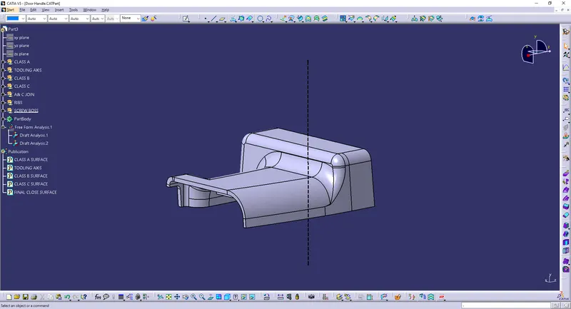
TOOLING AXIS:
- Considering the Ejection from the cavity of the mould after manufacturing the interior trim must have the nominal 3-degree draft angle.
- Hence the tooling axis is created by considering the above factor.
- The direction in which the mold or core and cavity opens is the tooling axis.
- In this case below is the tooling axis that I have used.
- The Line in the black color is our tooling axis.
RIB:
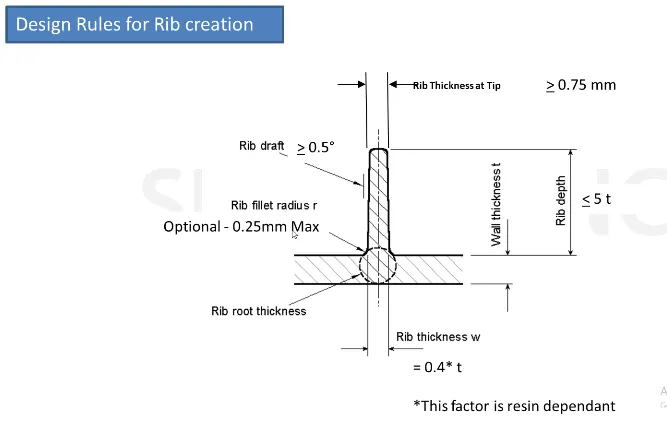
Rib provides an economical way to increase stiffness and strength to the mould parts without increasing the overall thickness of the wall. It is thin protrusion that extended perpendicular from the wall.
Design considersation of the Rib
SCREW BOSS:
Screw boss are used as a point for attachment and assembly, most common in as cylindrical projection with hole design to receive screw or other types of fastening hardware.
Design considersation of the Screw boss
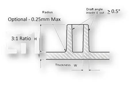
- Draft - 0.5 degrees on the walls of boss
- Thickness - Typically 40%* of the nominal wall at the base.
- Height to Diameter Ratio - 3:1
- Radii - 0.25mm maximum radii.
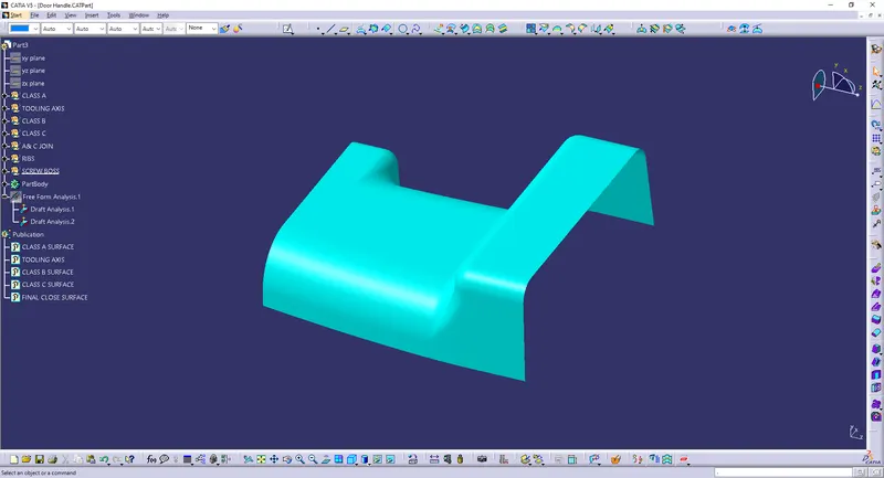
CLASS A SURFACE:
- In automotive design, a class A surface is any of a set of freeform surfaces of high efficiency and quality.
- It is the visible aesthetic surface of any automotive component.
- Class A surface refers to those surfaces which are visible and abide to the physical meaning, in a product.
- This classification is primarily used in the automotive and increasingly in consumer goods industry.
- It is a requirement where aesthetics has a significant contribution.
- For this reason, the exterior of automobiles is deemed Class-A.
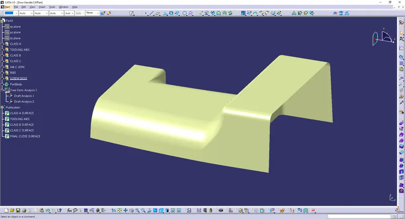
- Below is the CLASS SURFACE that I have used for this model.
CLASS B SURFACE:
- Class B surfaces are Engineering Surfaces which are invisible to the eyes or often on the back side of the Class A surfaces.
- It is mainly the thickness of the component or Class A.
- These surfaces need to be designed as per the Class A surface i.e., the continuity, thickness of the component, functionality etc should be maintained.
- These surfaces include the main engineering features such as Screw bosses, Ribs, Snaps, Stiffeners and fixations.
- B surfaces also do not contain any aesthetic styling content and textures since it is not visible to eyes.
- Below is the image of CLASS B that I have created.
CLASS C SURFACE:
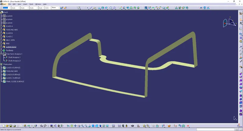
- Class C surfaces are connectors between Class A and B surfaces.
- This surface connects both A and B surfaces along the Tooling Axis.
- It contains the draft as per the design.
- It is basically the thickened surface between both A and B surface.
- Below is the Class C surface that I have created for this model.
CLOSED SURFACE:
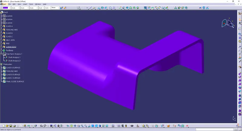
- Now the class – A and Class- C surfaces were joined together by removing the gaps in-between them with the help of extrapolation and Trim surface.
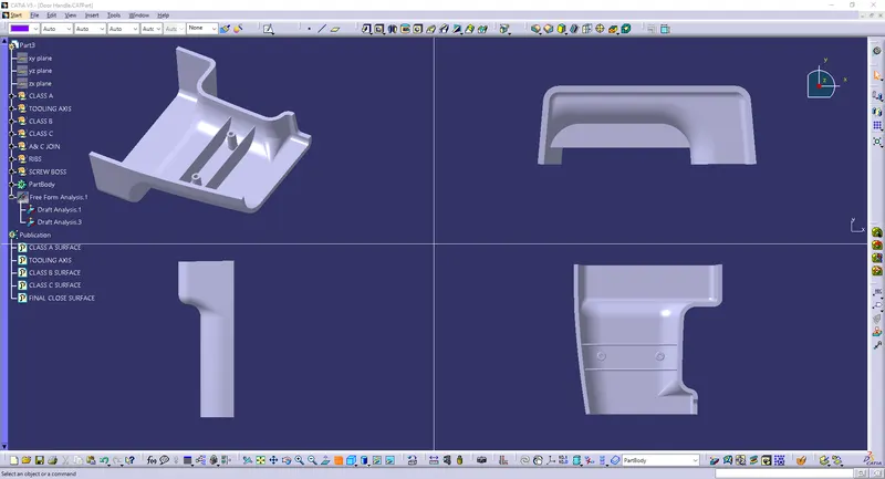
- Then, by defining the part body by using the Closed Surface command in Part Design, the component's solid body is created.
FINAL SOLID BODY:
DRAFT ANALYSIS:
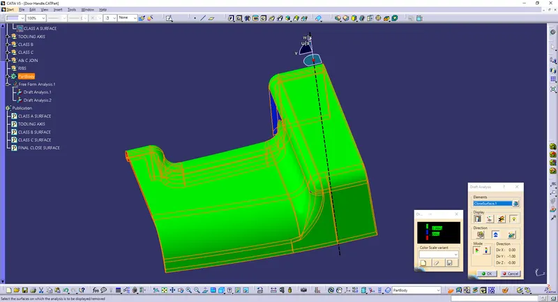
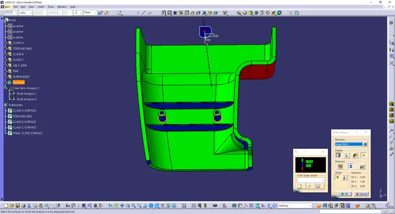
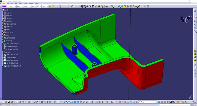
- Draft Analysis is a tool in CATIA which identifies the zones which deviates from the specified values of angles along a defined draft direction using colour codes.
- It highlights the regions of draft using colours.
- Draft analysis is the first step performed after receiving the Class A of the component.
- Draft analysis should be passed in order to make the plastic component manufacturable.
- Acceptable draft angles are used as range for draft analysis that is 0 to 3 degree.
SURFACE:

SOLID BODY:
CONCLUSION:
This reports concludes the creation of RIBS & SCREW BOSS by following all Design Consideration for this DOOR HANDLE.