Week 9 - Attachment Feature Creation (Ribs & Screw Boss) - Challenge 1
Object :- Design of Ribs and Screw Boss for Drill Handle following the design rules in given class A surface. And perform Rib root thickness analysis and draft analysis on the final component.
Introduction :- Drill handle is made from the plastic and this component is made by plastic molding process. And this is designed with the help of CATIA V5 software. Because it comes under surface design and CATIA is best to perform surface design and draft analysis. It has more accuracy than other.
Consider the thickness of the component 2.5 mm.
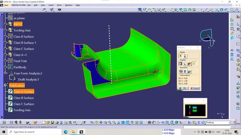
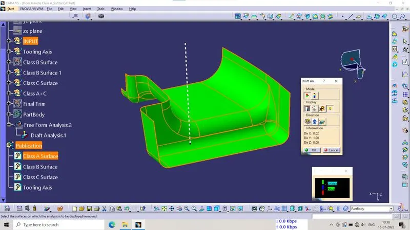
Draft Analysis of Class A Surface In CATIA :- It provides colour based identification. With the help of this we can easily find that which surface is in clear and which is in stuck by colour changing. Here I give the draft angle 3 degree. The result in colour based that the surface which green (means draft angle > 3 degree) is right. And where the colour is blue mean draft angle is 3 degree to 0 degree if this surface area is low then you can go. If you find red colour zone then it means draft angle is less than 0 degree. Then you will have to create tooling axis by another way if possible, otherwise you can say your design engineer to correct for designing.
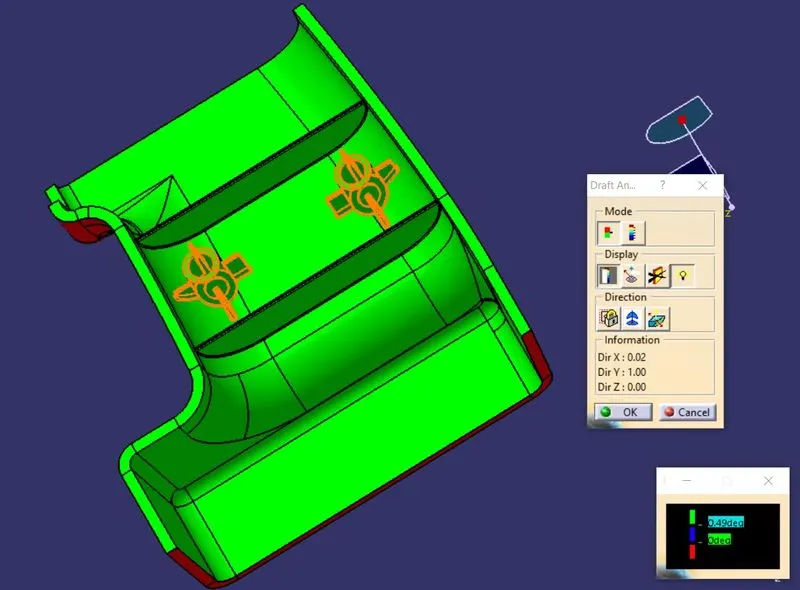
Here I give a 3 degree draft angle. But some area is looking blue which is not good. We can not change the design because it is Class A Surface which is designed by other team. We can only say to them for modification. When I give 0.5 degree draft angle then everything is fine. So it may be acceptable.
- When draft angle is 3 degree
- When draft angle is 0.5 degree
Rib Design :- Ribs provide a means to economical stiffness and strength in molded parts without increasing overall thickness. They also facilitate
- Locating and arresting components of an assembly,
- Providing alignment in mating parts,
- Acting as stops or guides for mechanisms.
Proper Rib design involves many issues which is consider carefully when designing-
- Thickness
- Height
- Location
- Quantity
- Manufacturability
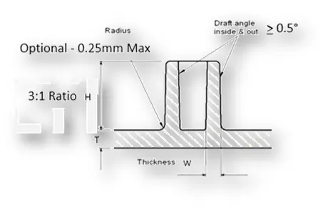
Guidelines for Ribs on Show Surfaces
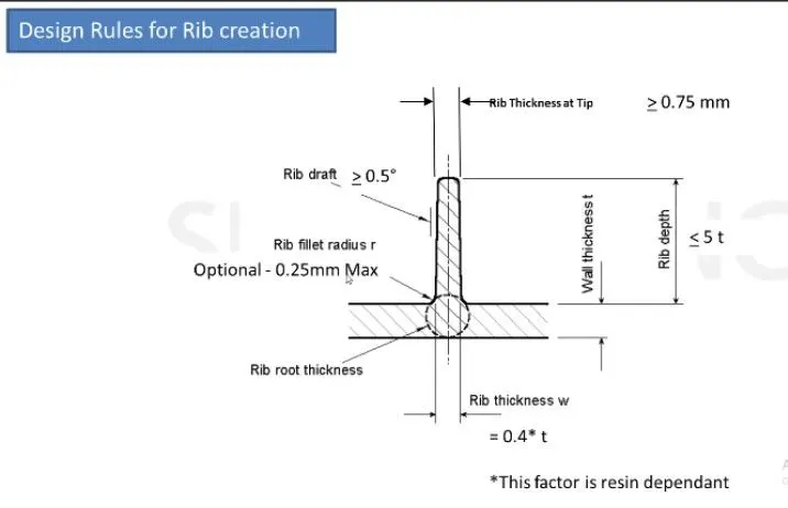
- Draft - 0.5 degree per side minimum
- Thickness - Typically 40% wall thickness
- Height ≤ 5 x wall thickness
- Spacing - 3:1-steel hieght / width ratio maximum
- Thickness at the top ≥ 0.75mm
- Optional Radius - 0.25mm maximum
- Rib root thickness should be under deviation of +-30% from the wall thickness
- Design Suggestions
Ribs should be spaced so that the steel between the ribs is at a
- Height / width ratio
- 3:1 steel
- 2:1 is preferred
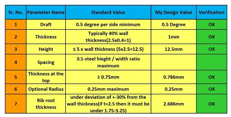
I have Designed the ribs which cross-section analysis is here for checking purpose that everything is ok or not. I fond that everything is ok.
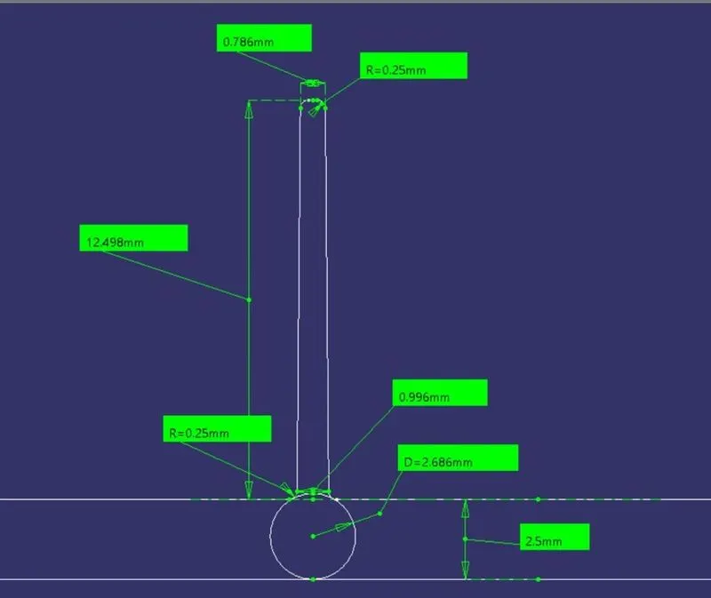
Analysis Chart For Easy Checking Purpose-
Screw Boss :-
Bosses find use in many part designs as points for attachment and assembly. The most common variety consists of cylindrical projection with holes designed to receive screws, threaded inserts, or other types of fastening hardware.
Design Rules For Screw Boss
General Guidelines for Bosses-
- Draft (0.5 degree on the walls of the boss)
- Thickness (W= 0.6xT)
- Height of Diameter Ratio=3:1 (H/B < 3)
- Optional Radii ( 0.25mm Maximum)
- Boss Gussets must meet rib guidelines
- Coring Out Bottom
- Planning ahead for type of ejection
- If less than 25mm tall, draft is not required when sleeve ejection is used
- Over 25 mm tall, draft is required on outside wall only if sleeve ejection is used
- If sleeve ejection is not used, draft is required on the wall.
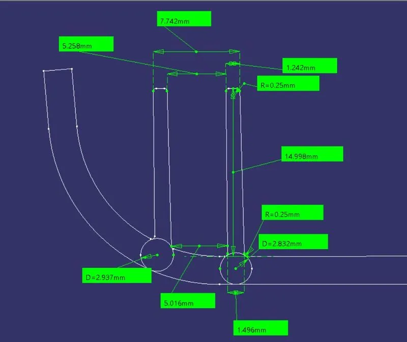
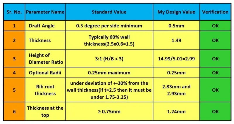
I have Designed the Screw Bossis for M6 thread which cross-section analysis is here for checking purpose that everything is ok or not. I fond that everything is ok.
Analysis Chart For Easy Checking Purpose-
Door Handle Component with Rib and Screw Bosses with Gussets :-
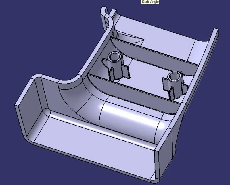
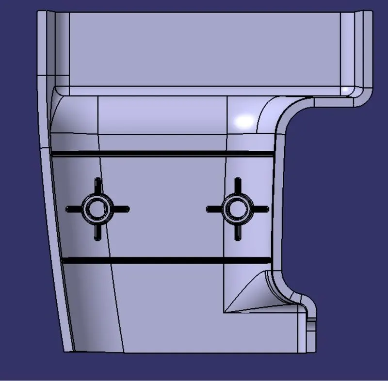
Draft Analysis :-
The Draft Analysis allows the user to easily analyze a part for proper draft angle. A Draft Angle describes the amount of taper for molded or cast parts perpendicular to the parting line. Draft Analysis is applicable for 3D part models. To create a draft analysis for any 3D part file, the user needs to select part/surface and select the pull direction. You can change the pull direction.
Draft Analysis of Door Handle :-
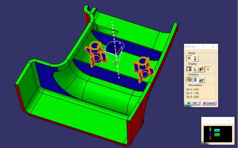
In above figure ribs, bosses and gussets are in blue because I have give 3 degree draft angle while in ribs, bosses and gussets have 0.5 degree draft angle. So in below figure I have given 0.49 degree draft angle for draft angle. So whole body is ok.
Conclusion :- In this project we learnt that how to create Ribs, Bosses and Gussets. Apart from this I learnt how to anylize that this ribs and bosses design is correct or not.
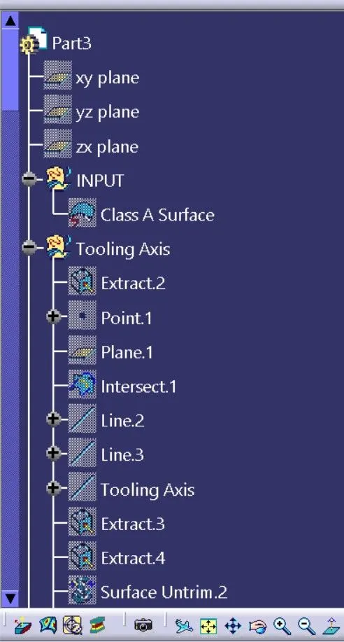
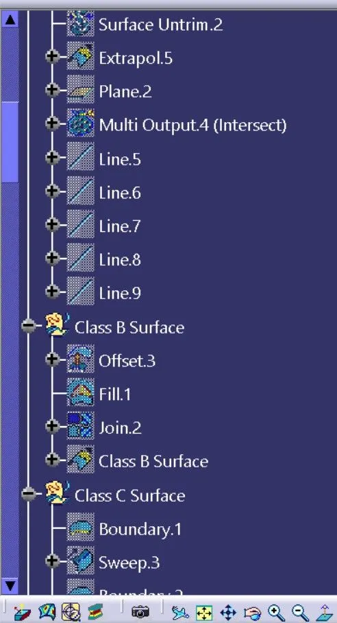
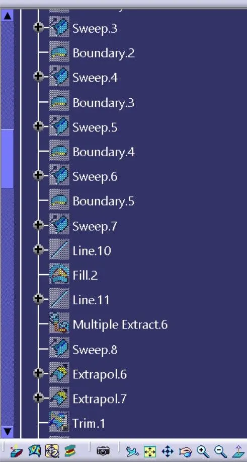
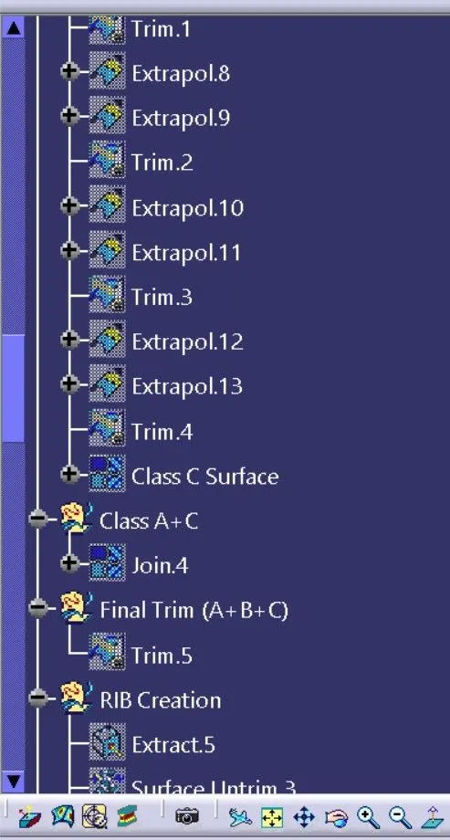
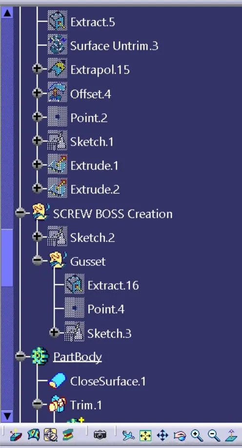
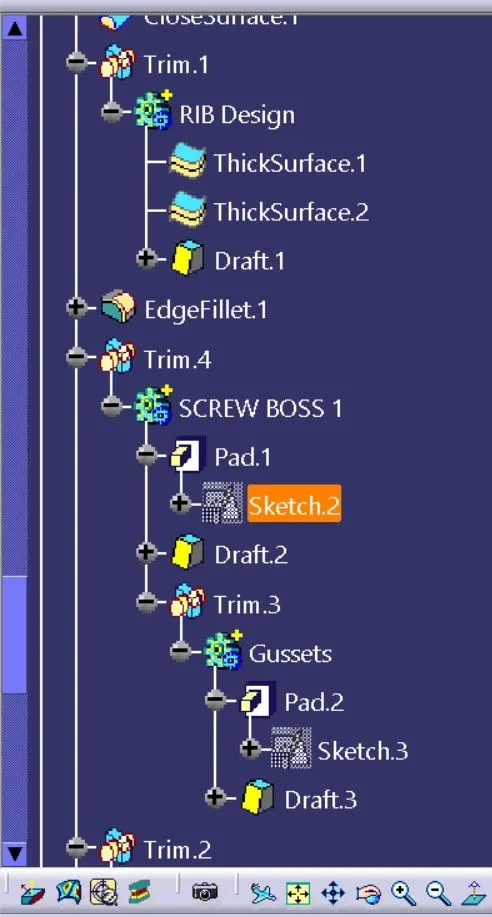
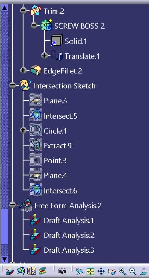
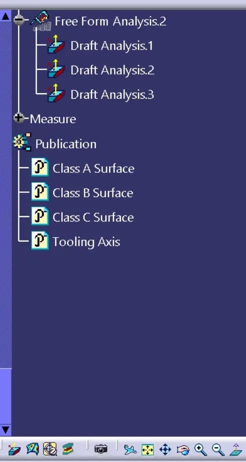
Feature Tree of This Part :-