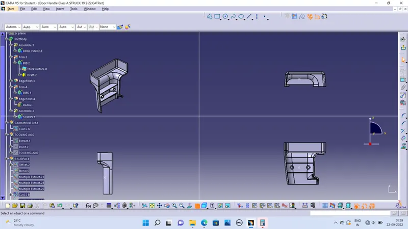
Week 9 - Attachment Feature Creation (Ribs & Screw Boss) - Challenge 1
Aim
Create the rib for the Drill Handle considering the design rules.
RIBS
Ribs are thin protrusions that extend perpendicular from a wall or plane to provide added stiffness and strength. They are thinner thsn primary walls and are used to support these walls as well as bosses by running perpendicular to these structure.
SCREW BOSS
Boss features are commonly found in injection molding designs. They are used to aid in the assembly of molded parts by providing a channel for a screw. Designing plastic screw bosses is fairly straightforward but there are a few considerations to ensure a strong connection between parts and mitigate cosmetic defects.
TOOLING DIRECTION
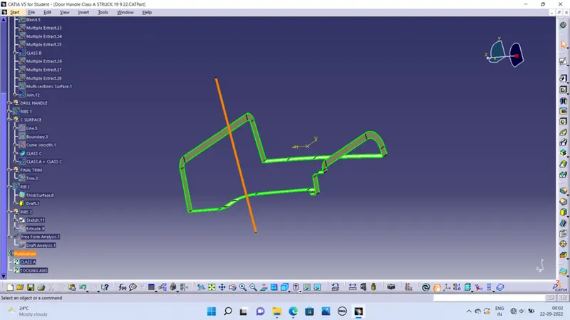
Arrange the view manually to check the best tooling direction which covers most of the surfaces. I extract a plane and make a point on plane and extend the line along y axis.
Class-B Surface
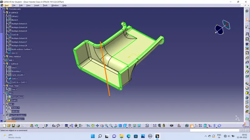
It means thickness of a part it is not visible and is inside part. In other words, Class-B surface is a surface below a certain thickness from the class-A surface. This is the surface that contains engineering feature.
Offset the class-A surface about 2.5mm inward direction.
Work on the patches created on the offset surface with the help of multi section surface features, blend etc.
Class C surface
Surface that joins class-A and class-B surfaces is class-C surface. Class C is often specified for interior surfaces not readily visible, surfaces that will be covered by another part when assembled
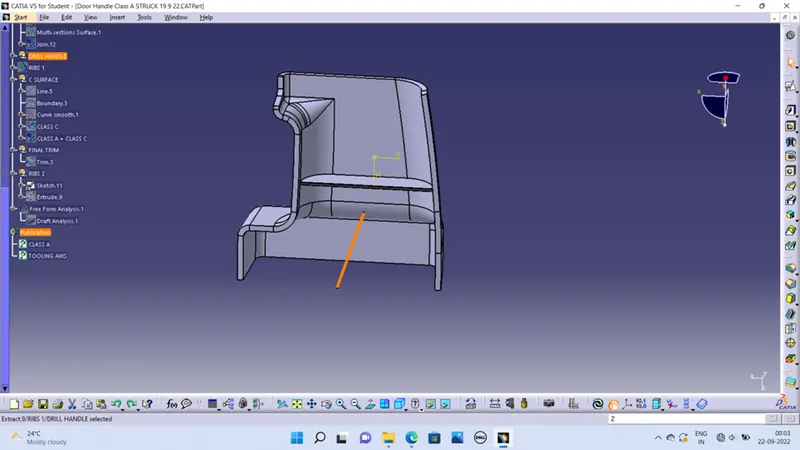
Ribs Design
Draft: 0.5 Degree per side (minimum)
Thickness of ribs: 40% of wall thickness
Height: 0.5*thickness
Spacing : 3:1- steel
Minimum thickness at the tip: 0.75
Radius: 0.25mm max
Rib root thickness should not be more than 30% of the wall thickness
Screw Boss creation
W= 0.6*T
Draft 0.5 Degree on both inside and outside walls of the screw boss.
Height to diameter ratio – 3:1
Radius(fillet) – 0.25mm
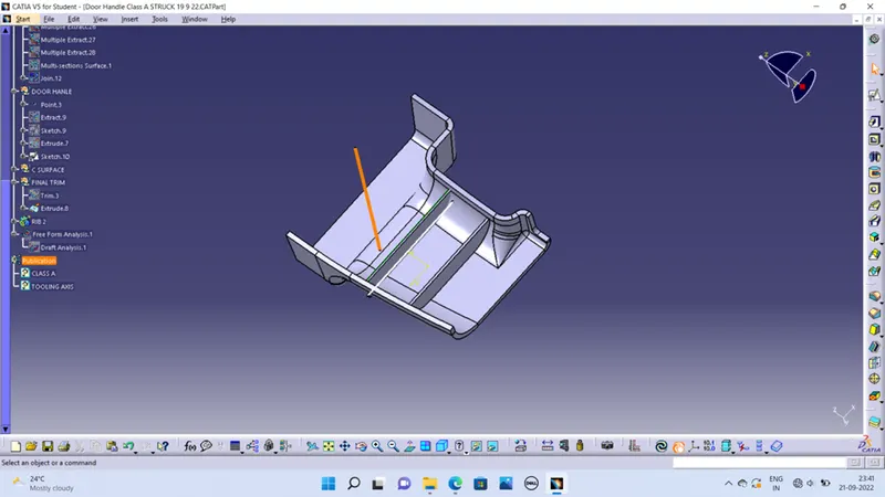
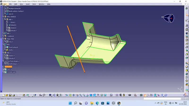
Rib Creation
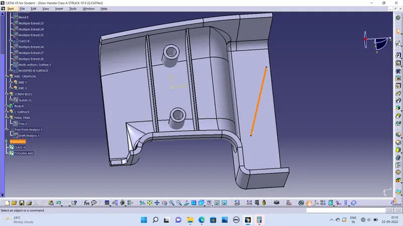
Create positioned sketch for the ribs and extrude the sketch with reference to the tooling axis or other method is create thicken pad with reference to the tooling axis.
Perform union of ribs with the drill handle part body
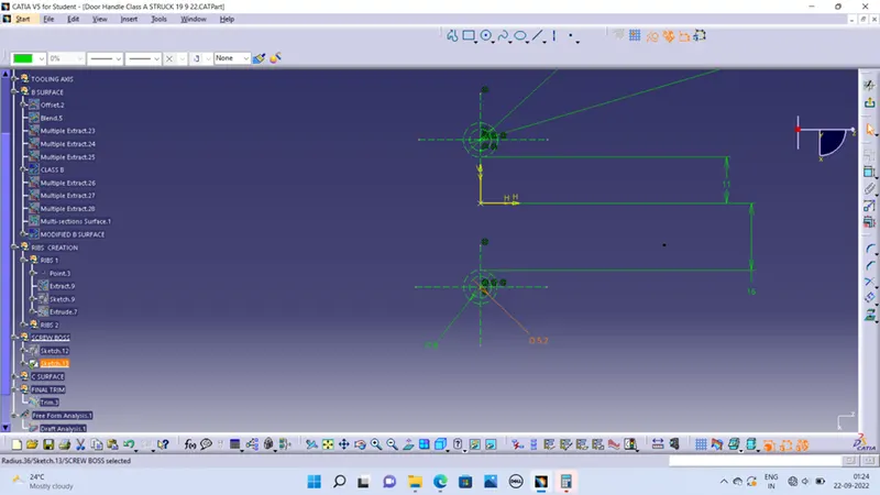
Screw Boss
Create sketch of screw boss and extrude it with reference to the tooling axis