Week 8 - Challenge 1 - Base Bracket Design
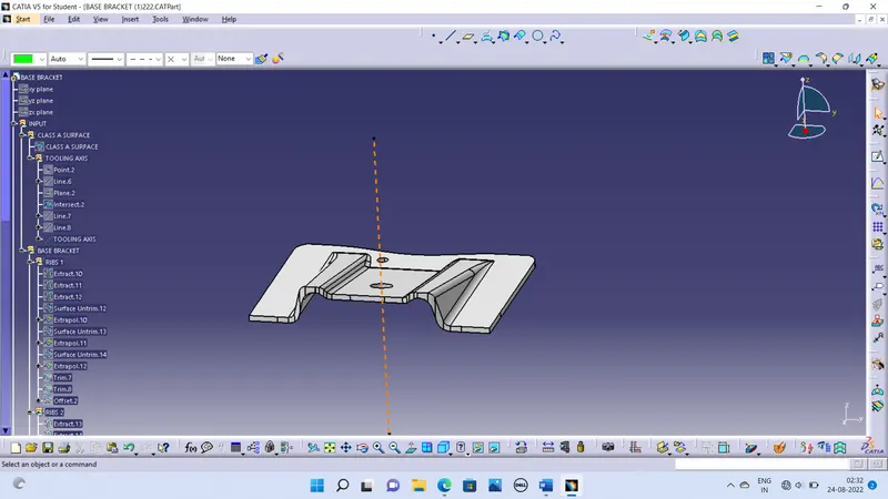
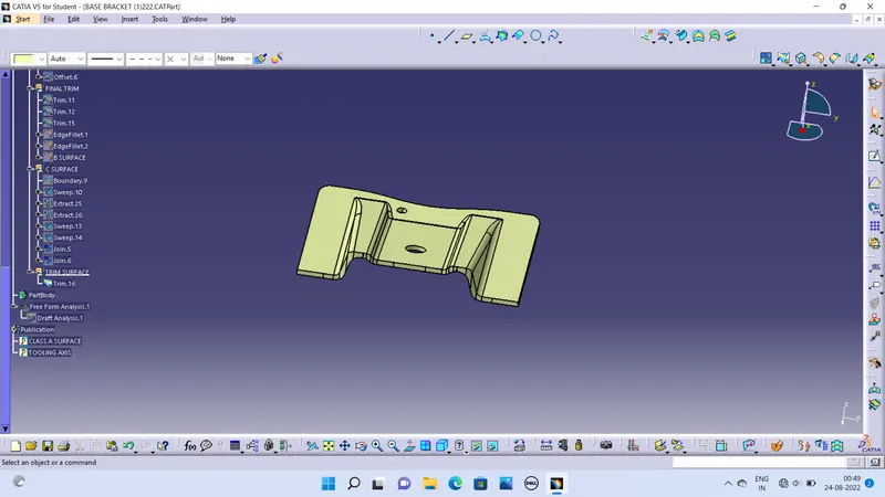
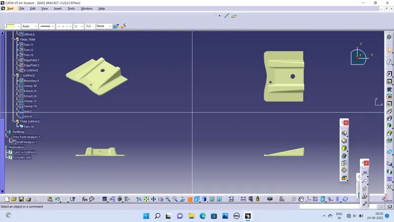
AIM: Create Base Bracket Plastic through given Class A Surface. To perform the draft analysis on model.
PROCEDURE:
- First of all check the gap if there is no gap between the surfaces by using boundary command.
- After that create a point using circle/sphere/ellipse centre option. Create a line using direction Z option.
- Create a plane with point created before and yz plane.
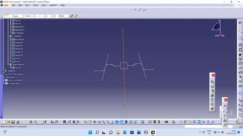
- An intersection sketch is made using YZ plane and the class A surface.
- By using a point-point line direction create a line along the sketch both the sides. Then bisecting selecting the two line the tooling axis is created.
TOOLING AXIS
- Its basically the direction that mold pulls apart. Its is built in two separate pieces, basically. You have a cavity side and core side. There are different method to find out the tooling direction. Her I used bisecting method ro find out tooling direction.
DRAFT ANALYSIS AND PROCEDURE
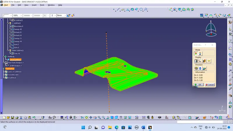
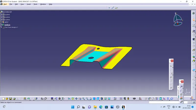
- Draft Analysis Draft analysis helps to detect if your drafted part is easily removable from the mold (in case of plastic component) or die ( in case of plastic component). All plastic component should be minimum draft 3 degree
- Normal draft angle is 3 degree but 7 degree is allowed for the subassemblies like ribs and slots.
- Insert- analysis- feature draft analysis.
- First the compass should be placed on the tooling axis. check it align with model or not then lock the draft direction using lock feature.
- Color chart indicates the various condition of draft angle if show shows green then my part passed and can be ready for manufacture.
CREATE CLASS B SURFACE
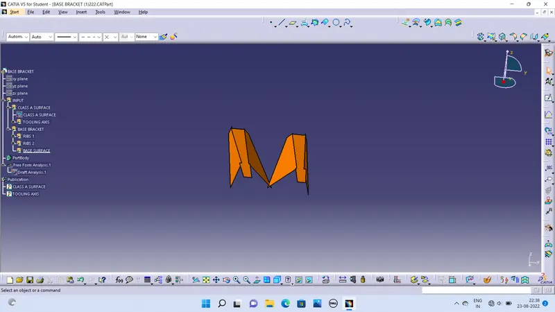
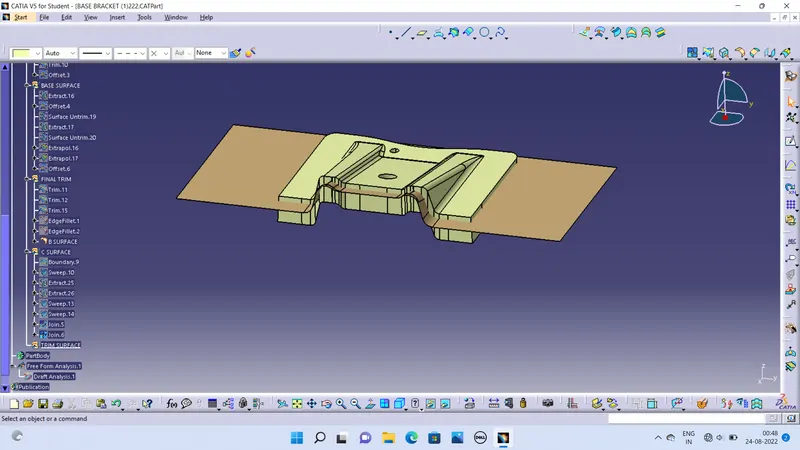
- Extract the both side and top surface of first rib with no propagation Then untrim one by one and hide the extract.
- Extrapolate all the untrimmed surfaces one by one.
- Now trim the first and second surface then trim trim 1 with third surface.
- Offset the surface for 2.5mm downward
- Repeat the same process for ribs 2.
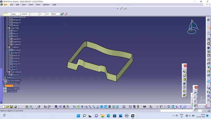
CLASS C SURFACE
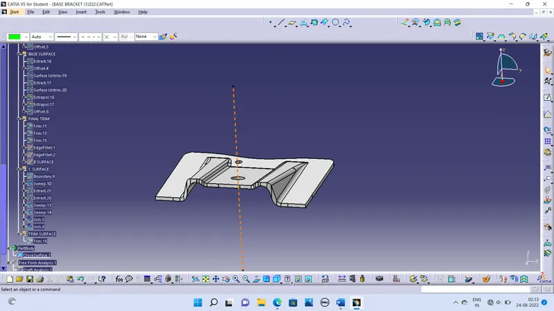
- Boundary the class A Surface as well as for two holes.
- Sweep (Draft with direction) boundary one by one by tooling axis with only 3 degree draft angle.
- Using join option to combine all the swept surface.
- Trims the joined surface with the Class B Surface to form Class C surface.
PUBLICATIONS
- Tooling axis – publication
- Select the base bracket (Class A surface)
- Sweep (Draft with direction) boundary one by one by tooling axis with only 3 degree draft angle.
- Using join option to combine all the swept surface.
- Trims the joined surface with the Class B Surface to form Class C surface.