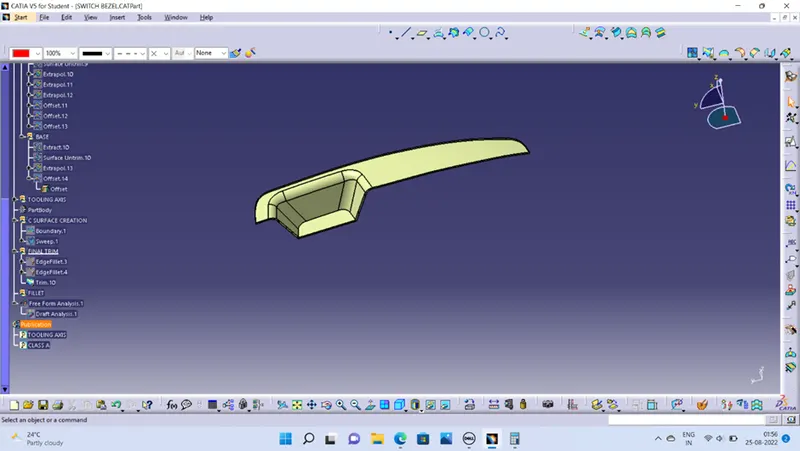
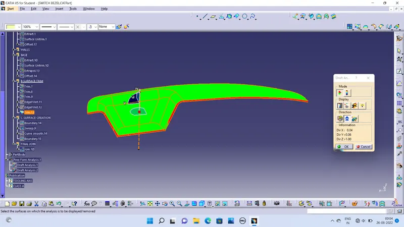
Week 8 - Challenge 2 - Switch Bezel Design
OBJECTIVE
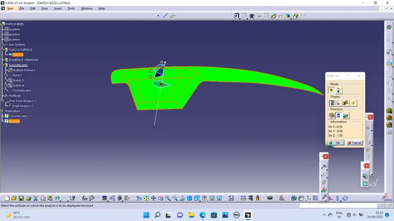
To create design the switch bezel and to do a draft analysis .
DESIGN CONSIDERATION
Class – A surface are created on all visible exterior surfaces using alias.
Class – B surface have engineering feature like ribs etc.
Class – C surface should be pass on draft analysis.
CREATION OF TOOLING DIRECTION
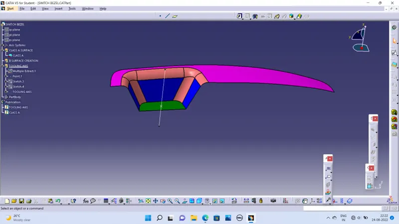
The base surface of the class – A was multi extract and a point at the centre is created and an axis system was inserted to the point and make sure not to select current feature.
Make sketch 1 along yz plane is created.
Now the same procedure is done along the xz plane but on one side we don’t have inclined lines so the centre point is used to extrude a line along the z-direction and gave a measurement of 5 degrees (Tentatively).
With these two lines from sketches 1 and 2, the bisecting line is created.
CREATION OF B SURFACE
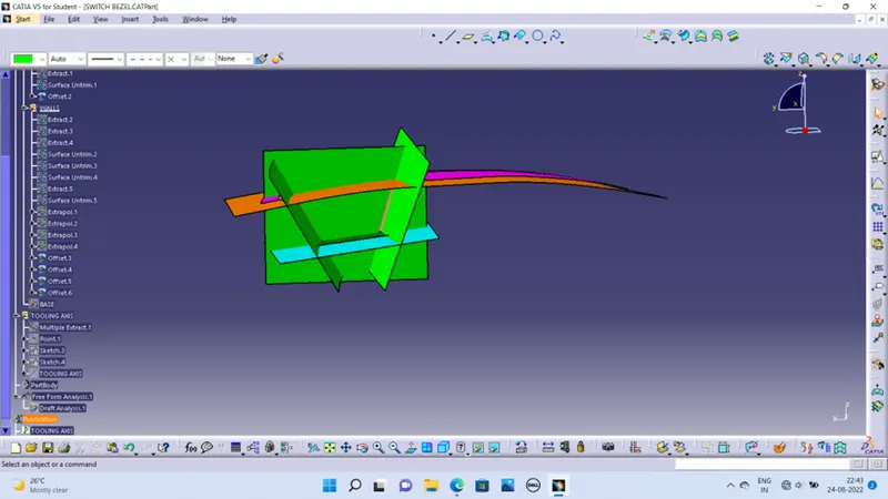
For creating the class-B surface the required surface except the offset surface have been extracted and then untrimmed all the surface.
Then all the surfaces have been extrapolated to get intersections between them.
Since the thickness of the Switch bezel is 2.5mm the B-Surface was offset to 2.5 mm downward the required corners have been filleted to 12.5mm (14mm-2.5mm).
if offset is outside then (Ex 14mm + 2.5mm), if offset is inside then (Ex 14mm -2.5mm)
CREATION OF CLASS C SURFACE
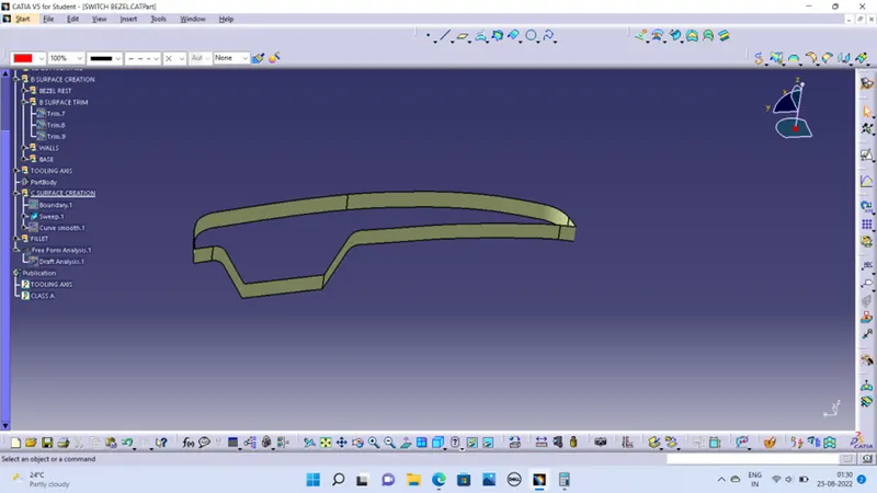
Select outer edges of the A-Surface were extracted using Boundary.
Then for avoiding the patches the curve is smoothened using the Curve Smooth option.
Then by using the sweep command the surface was created with the following feature controls
Profile type -Line
Subtype – With Draft Direction
Guide Curve – Smooth Curve
Draft Direction – Tooling AxisDraft Computation
Mode – Square
Angle – 3 Degree
Angle Sector – Positive Downward
Length – 20mm