Week 9 - Attachment Feature Creation (Ribs & Screw Boss) - Challenge 1
TO DESIGN A RIB AND SCREW BOSS OF A DOOR HANDLE BY USING CLASS A SURFACE
AIM:
- To design a door handle Plastic component through the given Class-A surface by creating a tooling axis and draft analysis of the given surface and also design a rib and screw boss.
DESIGN PROCEDURE:
- To setup the class-A surface and to creating a tooling axis
- add draft angle
- To create a base surface of model
- To create a B-surface
- To create a C-surface
- To use close surface for creating a solid part model
CLASS-A SURFACE:
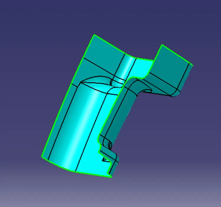
TOOLING AXIS:
- Tooling axis can be classified into two methods
- Bisecting method:
- It is defined as the direction in which the Mould/core and cavity open. Selection of the direction of the tooling axis depends on the ease at which components can be easily ejected.
- By analyzing the component, the most easily eject able direction is somewhere close to the Z direction, (might be inclined to it) so we have made a sketch on the YZ plane of Axis System) to create a bisecting line considering the 2 faces which might be difficult to be tooled.
- To bisect the lines and point by creating a tooling axis.
- general and reference method:
- It can create based on the origin and calculating manufacturing process based on the point orientation for setting up tool.
DRAFT ANALYSIS:
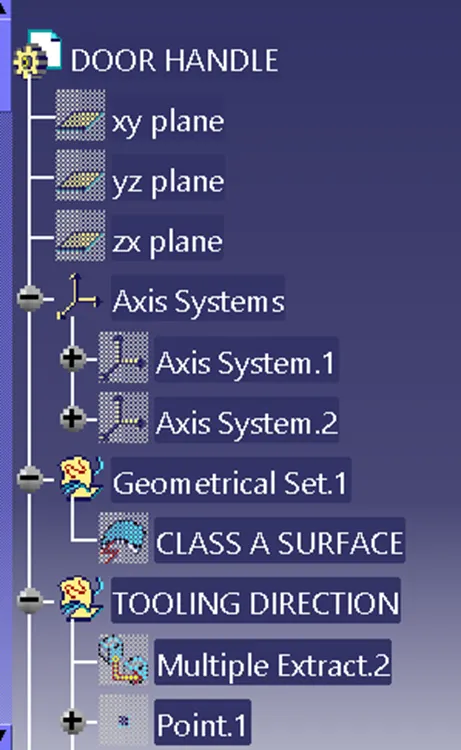
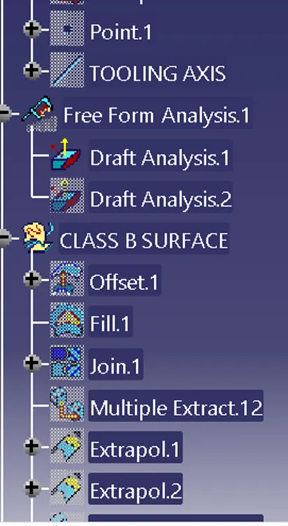
- The Drafting analysis was performed on the class-A surface by using the Feature Draft Analysis
- Using this command, the compass was set on the main tooling axis and the Draft angle was changed to 3 degrees.
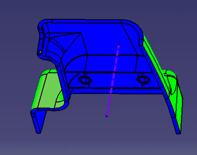
-
CREATING CLASS-B SURFACE:
- To offset the class-A surface along 2.5mm for to create a B- SURFCAE.
- Surface Gaps can be filled by using a fill tool and multi sectional tool

- B-SURFACE
-
CREATING C- SURFACE:
- To use multiple extract tool on the class A surface
- The extract boundaries can be sweep at 90 degrees to the reference boundaries up to required length
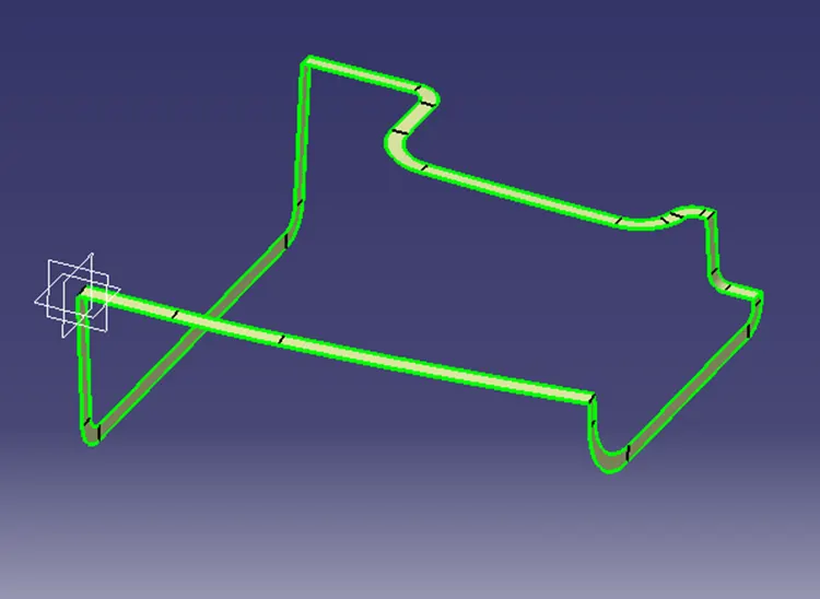
C-SURFACE
SURFACE MODEL OF A DOOR HANDLE:
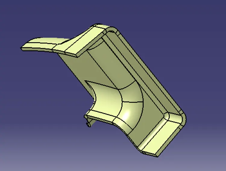
Without rib and screw boss
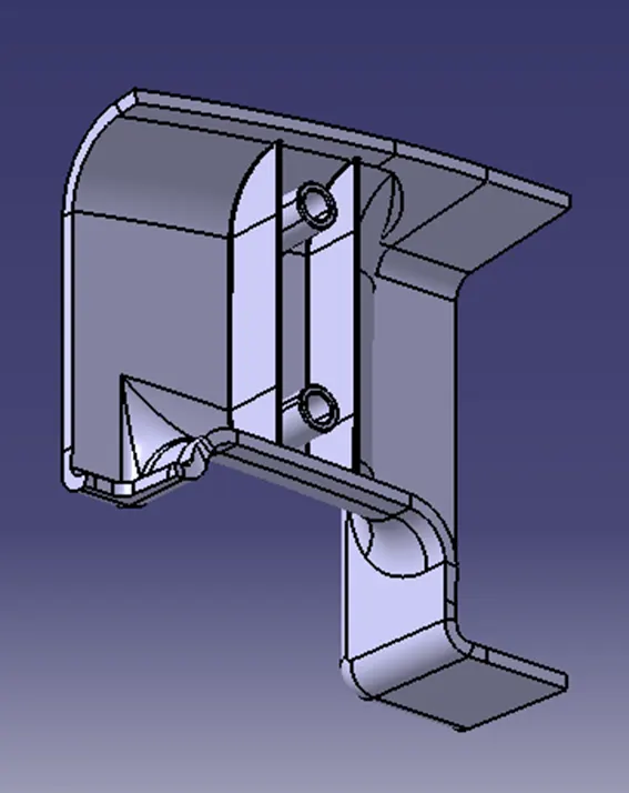
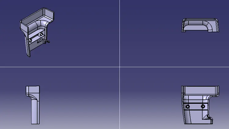
SOLID MODEL OF A DOOR HANDLE WITH RIB AND SCREW BOSS:
TREE SHOTS:
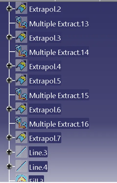
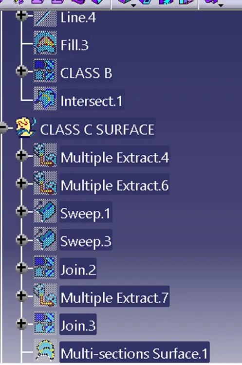
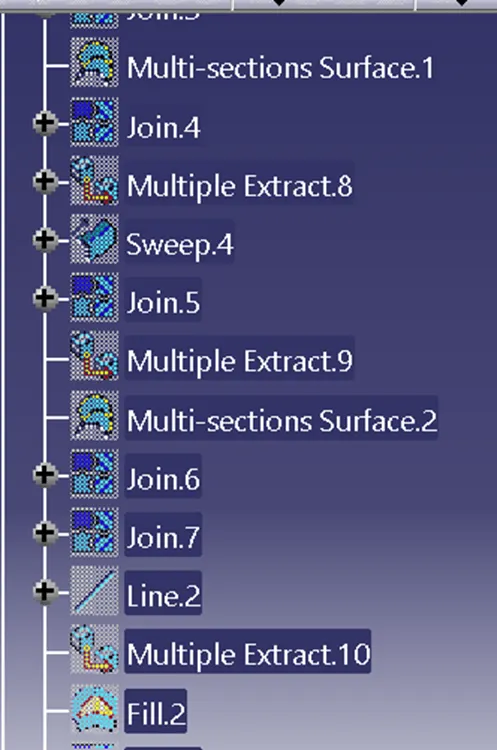
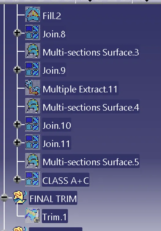
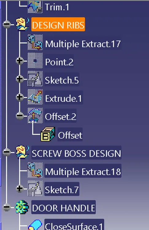
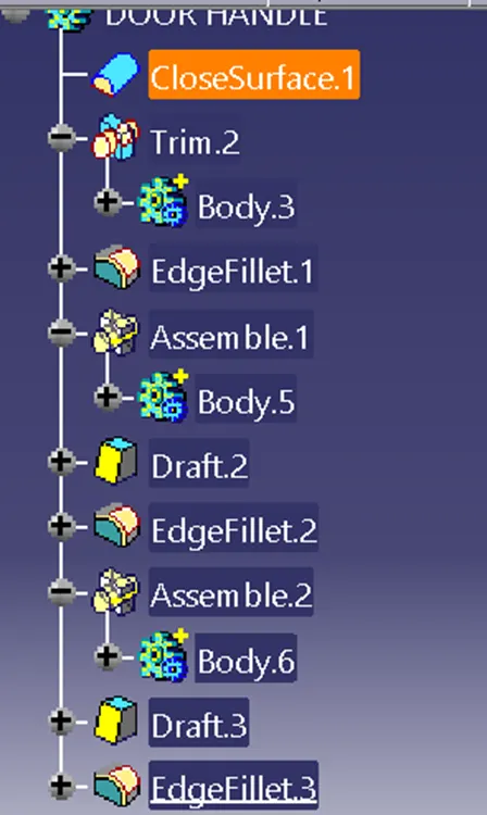
DESIGN OF RIB AND SCREW BOSS:
- To design a rib based on the requirement of a component and to add set of calculations for construction of rib and screw boss
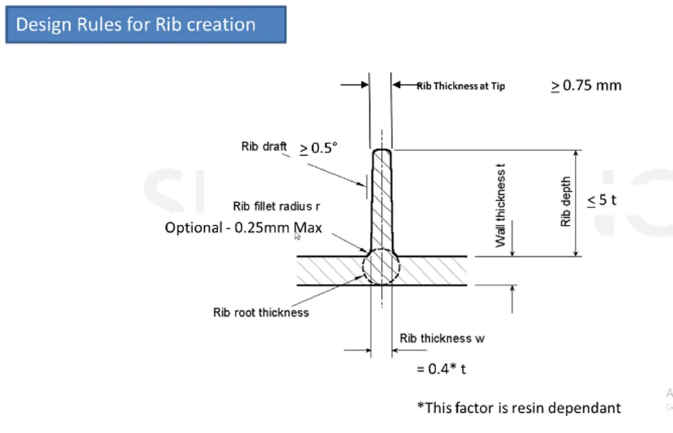
Design Principle for Rib Creation
- Ribs are thin wall protrusions that extend perpendicularly from a wall or plane.
- They are usually found in clusters offering support to a plane that would have otherwise been too thick, but can also be stand-alone support for a single wall.
- They are commonly used to provide additional support and strength to a part. Thickness and location are essential to rib design.
- First, the base surface where the rib has to be created is extracted using the Extract command. A positioned sketch is created and the profile for the rib is drawn.
Next, the profile is extruded, to find the height(h)=Wall thickness * 5
=3*5
= 15 mm
- Therefore, the height is 15 mm
- The extruded surface is thickened,
Thickness of rib(w)=0.4*t
=0.4* 3
=1.2mm
- Therefore, the thickness of the rib is 1.2 mm
- Draft angle can be set into 0.5 degree
CONCLUSION:
- To use class-A surface and create Tooling axis, Draft analysis were performed.
- The solid component was created from the surface model.
ISO CONSTRAINS OF RIB AND SCREW BOSS SKETCHES:
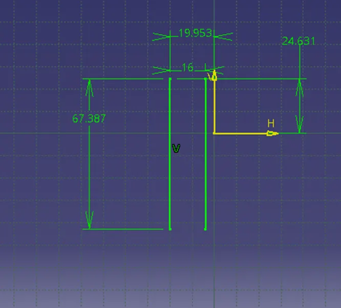
Rib iso sketch
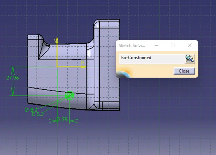
Screw boss iso