Week 9 - Attachment Feature Creation (Ribs & Screw Boss) - Challenge 1
Report
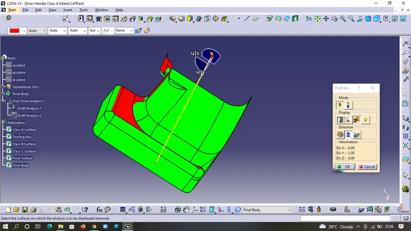
In order to create a tooling axis we need to first look for any hole or pocket or flat surface, in this case we have a flat surface(hit & trail method) from which we will take the perpendicular line
In order to make the perpendicular line we need to extract the base and take the center point and then make the line.
After making the line check for any lines parallel to it. If no plan found parallel (less than 3 degree draft), then mark the line as the tooling axis, (In this Class A Surface which we were given need some modification as no surface was found which is giving 3 degree draft on all the surface so i have chosen the best fit for the tooling axis)
Screenshots of the completed design in various orientations (Isometric, Front, Side, and Top View)
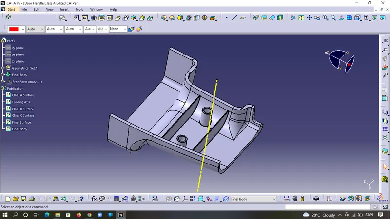
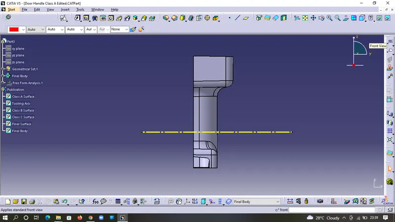
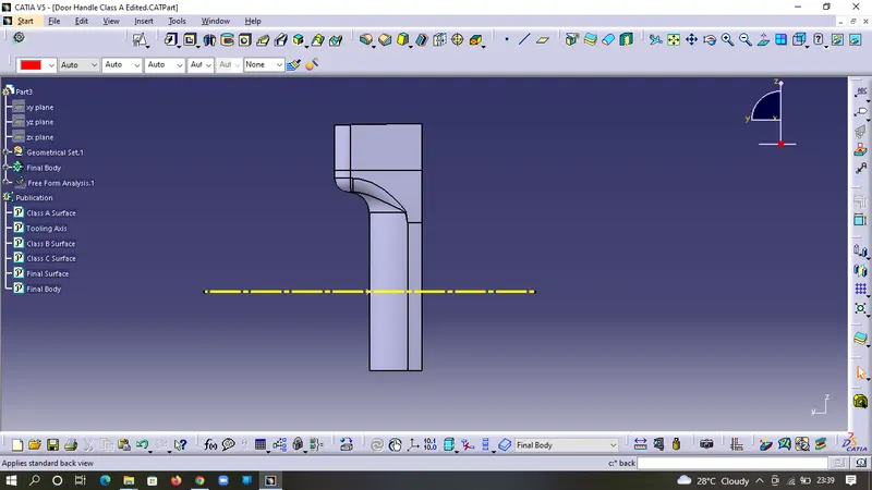
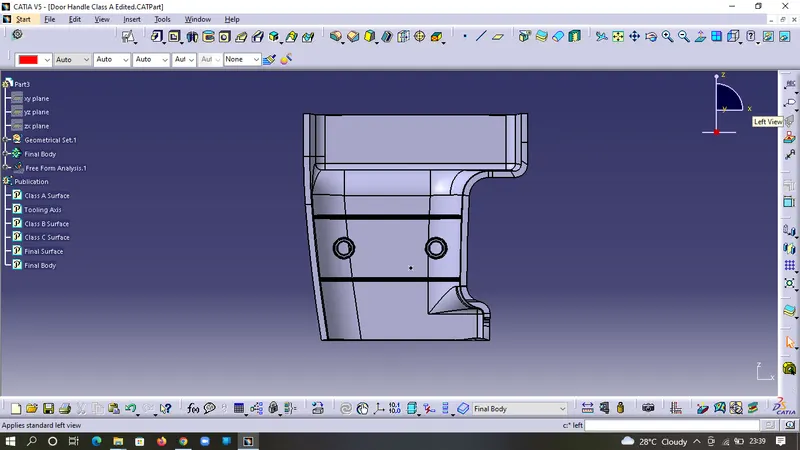
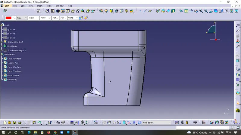
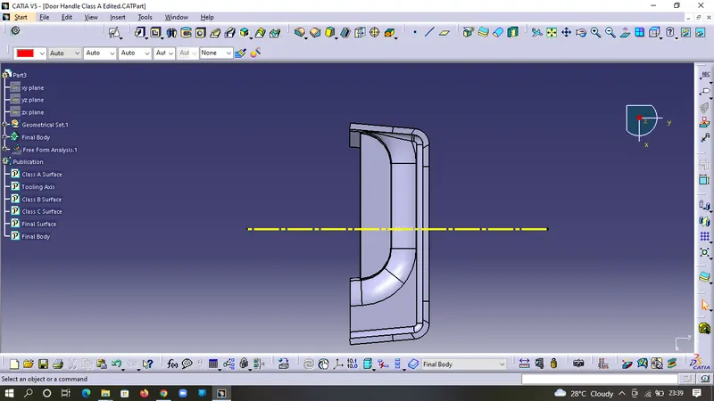
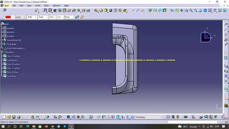
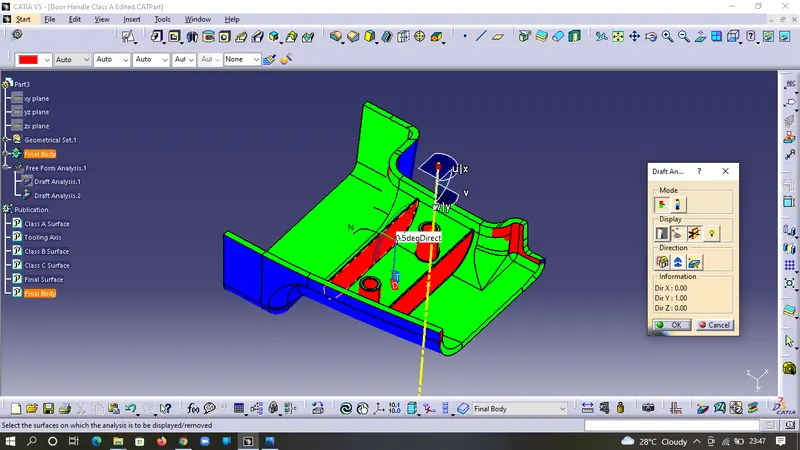
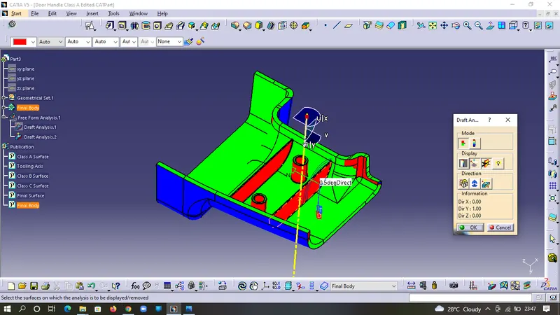
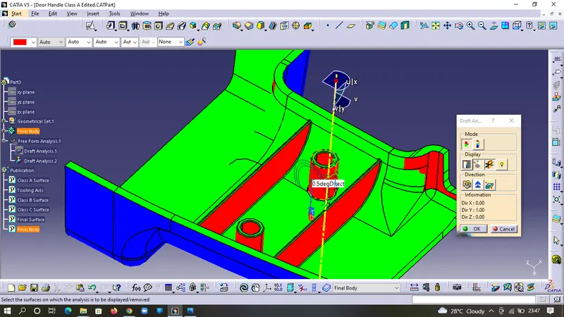
Draft Analysis On Final Component
In the draft analysis of the final part we can see that the draft angle on the rib and the screw boss is 0.5 degree as per design rules.