Week 9 - Attachment Feature Creation (Ribs & Screw Boss) - Challenge 1
RIBS & SCREW BOSS CREATION
AIM: To design ribs & screw boss on the Drill handle considering every RIB design rule in the industry.
Introduction:
Class-B surface contains all the engineer data required for the model to be completed. Some of the major features of the B-side are:
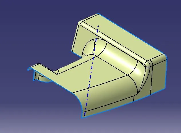
- Ribs
- Screw boss design
Rib & Screw Boss are the Engineering Features which is on "B surface”, they have some Design Rules to avoid Plastic defects.
1) RIBS: - Ribs are usually design to Improve Strength of Plastic Part without increasing the thickness of the component.
2) ScrewBoss: - It helps to screw component together. Screws are secondary features which are on B surface. Bosses are used to attach& assembly features of many component.
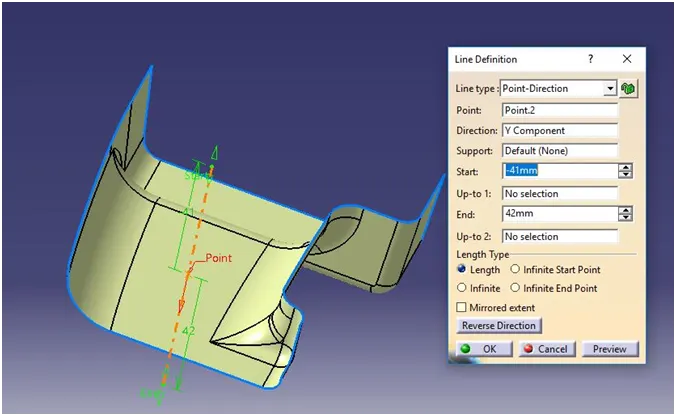
TOOLING AXIS:-The Tooling Direction is basically the direction that the mold pulls apart.The mold is built in two seperate pieces. Basically we have a Cavity & Core side.The Core pulls apart from the Cavity
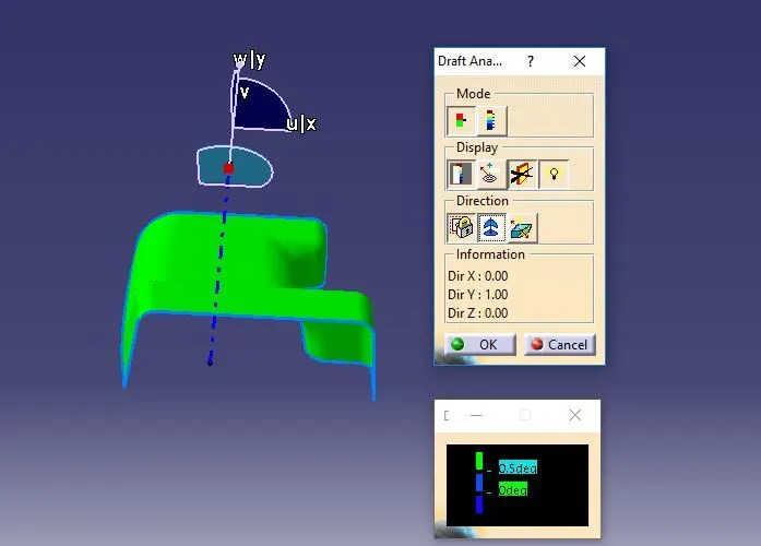
DRAFT ANALYSIS CLASS A SURFACE:- Draft analysis is required to check if a part has required draft or not. The Draft analysis refers to a Tool that allows us to determine if we can remove the part we are designing from the tool being used to design it.
RIBS:
They increase the stiffness and strength without increasing overall wall thickness of the model which is not desired. They also facilitate as Locator and arrest components of an assembly. Providing alignment in mating parts and acting as stopper or guides for mechanisms.
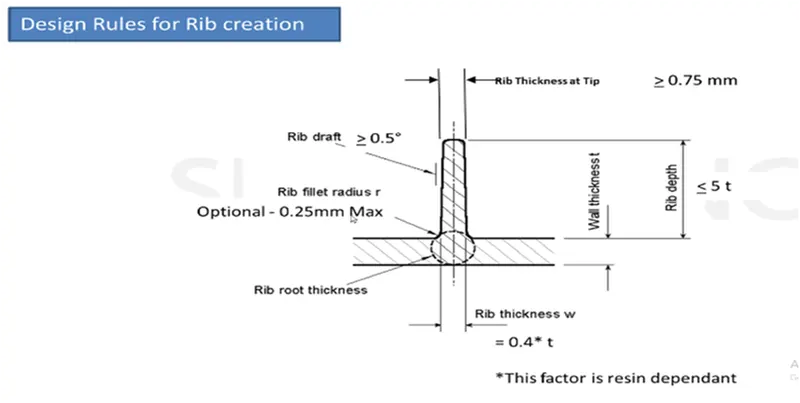
DESIGN RULES FOR RIBS:
APPROACH:
Ribs are thin wall protrusions that extend perpendicularly from a wall or plane. They are usually found in clusters offering support to a plane that would have otherwise been too thick, but can also be stand-alone support for a single wall. They are commonly used to provide additional support and strength to a part. Thickness and location are essential to rib design.
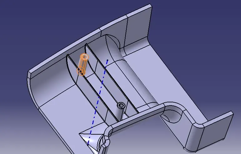
First, the base surface where the rib has to be created is extracted using the Extract command. A positioned sketch is created and the profile for the rib is drawn
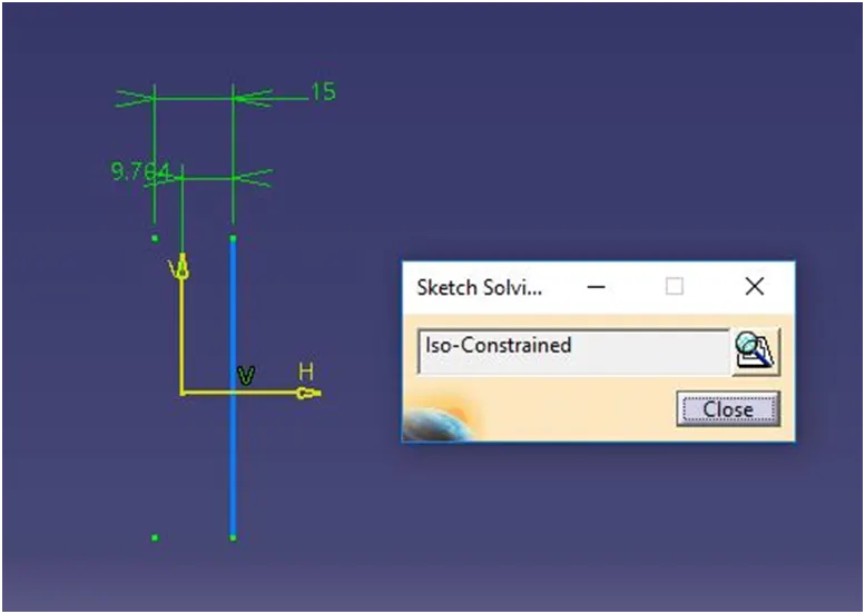
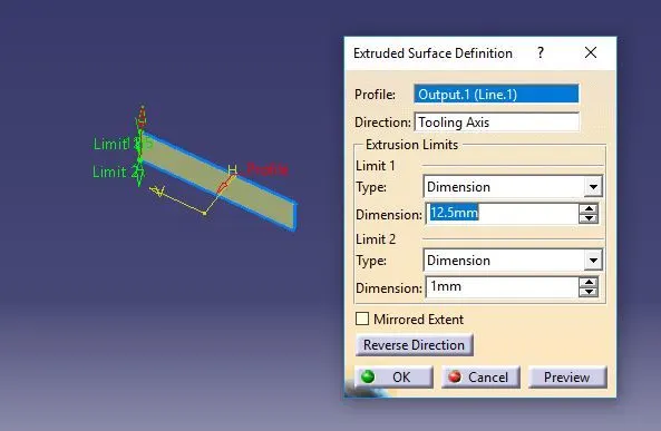
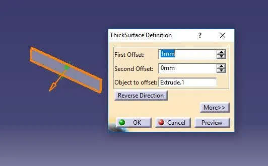
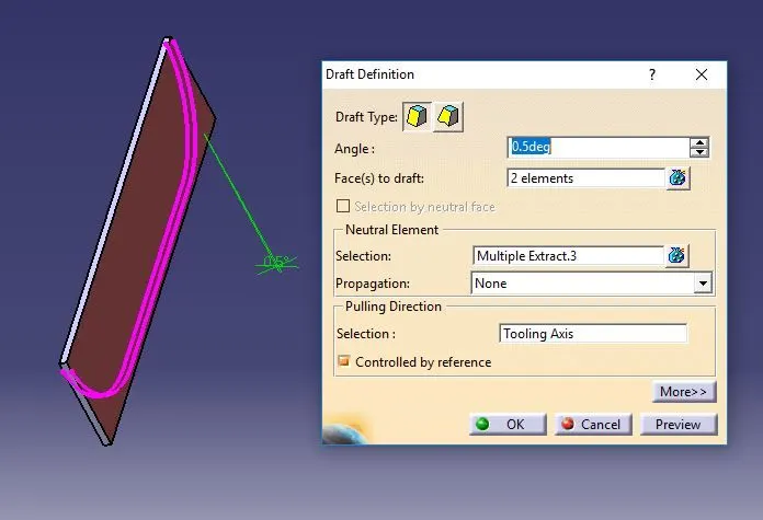
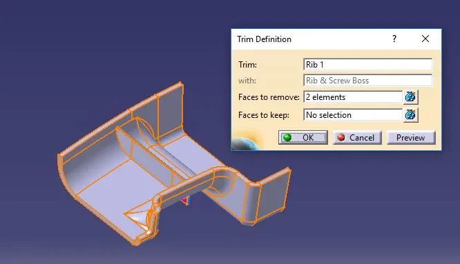
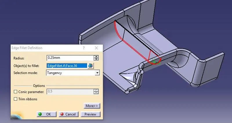
NOTE: After Creating Rib 1 Same procedure follow for creating Rib 2
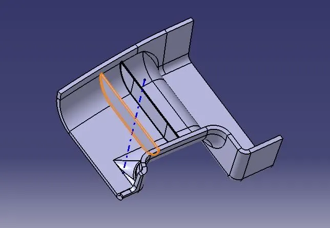
Screw Bosses:
It helps to screw component together. Screws are secondary features which are on B surface. Bosses are used to attach& assembly features of many component.
Approach:
Create the Screw boss for the Drill Handle considering the design rules mentioned in the video.
General Guidelines for Bosses:
- Draft - 0.5 degrees on the walls of boss
- Thickness - Typically 40%* of the nominal wall at the base.
- Height to Diameter Ratio - 3:1
- Radii - 0.25mm maximum radii.
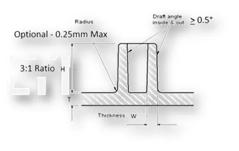
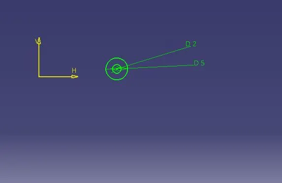
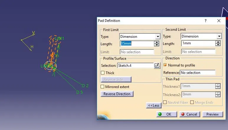
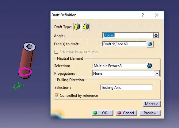
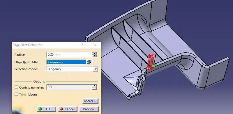
NOTE: After Creating Screw Boss 1 Same procedure follow for creating Screw Boss 2
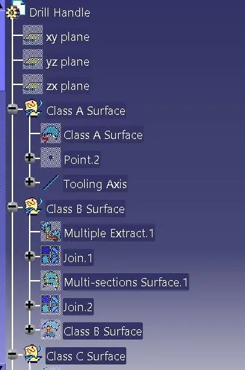
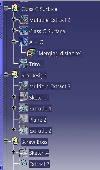
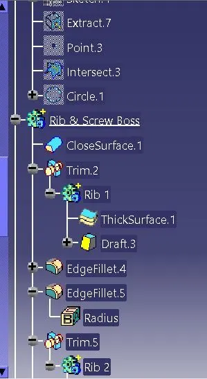
Feature Tree:
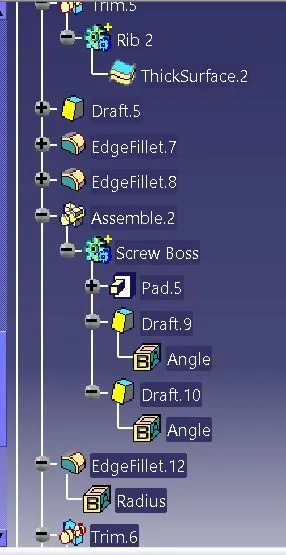
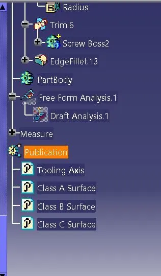
Different Views:
1) Isometric View:
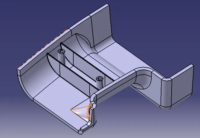
2) Top View:
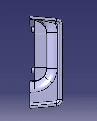
3) Front View:
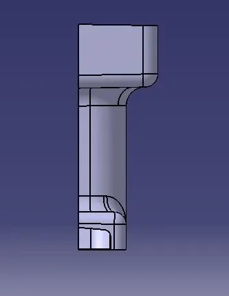
4) Left side view:
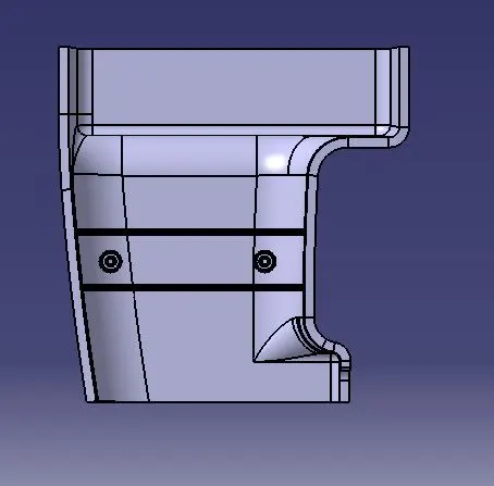
Conclusion: Thus i have created the Ribs & Screw boss on drill handle by following all design rules.