Week 9 - Attachment Feature Creation (Ribs & Screw Boss) - Challenge 1
Note:- As I am using Latest version of Catia,the MODEL is checked in session.
- AIM:- TO CREATE THE RIB FOR THE DRILL HANDLE CONSIDERING DESIGN RULE.
- Rib & Screw Boss are the Engineering Features which is on "B surface",They have some Design Rules to avoid Plastic defects.
1)RIBS:- Ribs are usually design to Improve Strengtth of Plastic Part without increasing the thickness of the component.
2)Screw Boss :- It helps to screw component together.Screws are secondary features which is on B surface.Bosses are used to attached & assembly features of many component.
DRAFT ANALYSIS:- Draft analysis is required to check if a part has required draft or not.The Draft analysis refers to a Tool thta allows us to determine if we can remove the part we are designing from the tool being used to design it.
Here I did Draft analysis with two values.Below I will show the difference through picture.
1) Draft angle used: 2.9
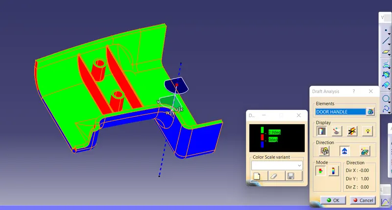
The surface is not clearing on closed body when I used 2.9 Draft angle for above case.
2)Draft angle used 0.4:-
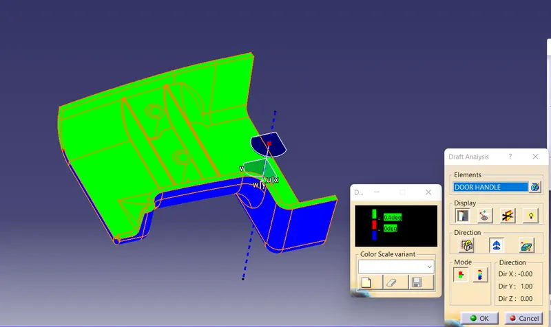
The surface is clearing on closed body when used 0.4 Draft angle in 2nd case.
TOOLING AXIS:-The Tooling Direction is basically the direction that the mold pulls apart.The mold is built in two seperate pieces. Basically We have a Cavity & Core side.The Core pulls apart from the Cavity.
Here, I have used Normal To Surface Method.
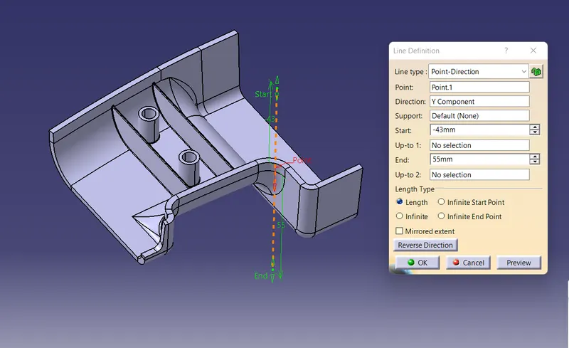
- ALL VIEWS & FEATURE TREE ARE AS FOLLOW:
- ISO VIEW
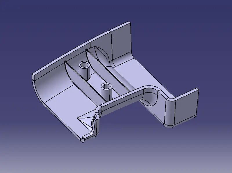
- FRONT VIEW
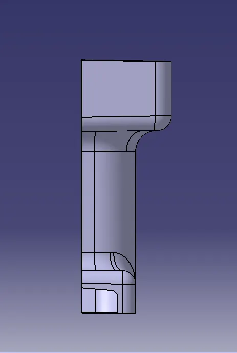
- SIDE VIEW
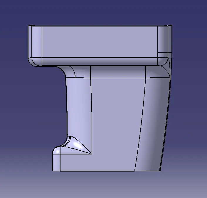
- TOP VIEW
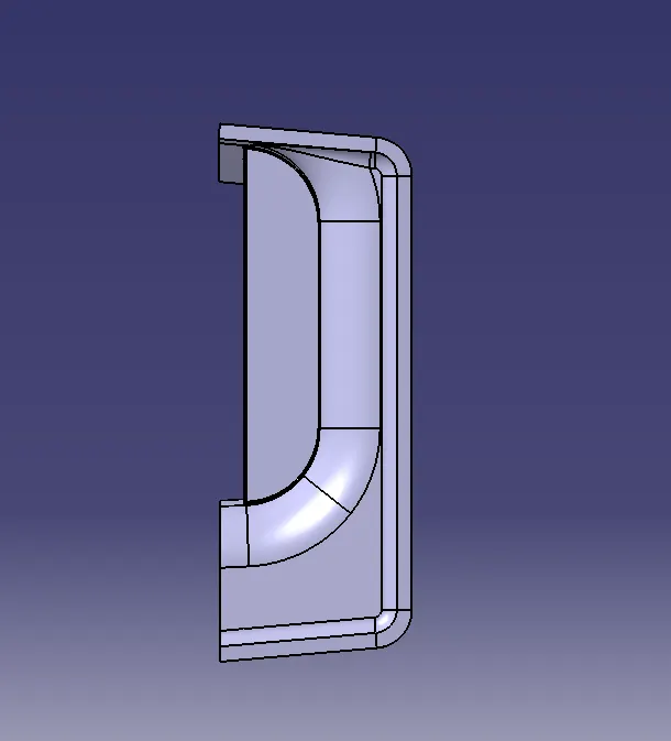
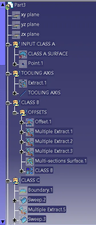
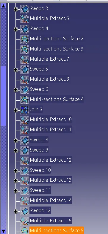
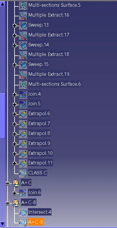
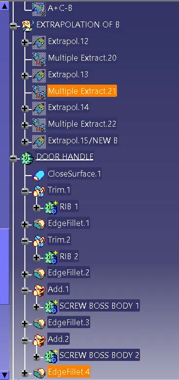
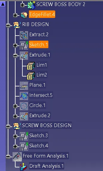
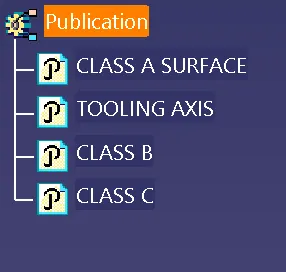
- PUBLICATION
- As per Design Rule I got the following Intersection:-