Week 9 - Attachment Feature Creation (Ribs & Screw Boss) - Challenge 1
Aim:
To Design Ribs and Screw Boss for Door Handle with a given class A surface by following the design rules and to perform draft analysis on the final component using CATIA V5 tool.
Objectives:
- To create a Tooling Axis.
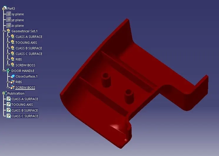
- To create Ribs
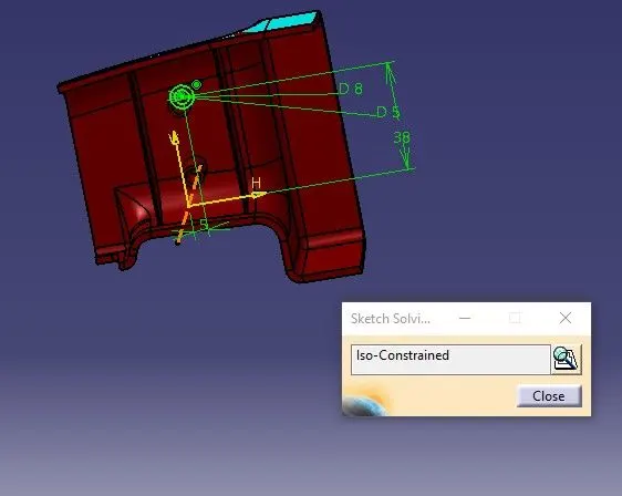
- To create Screw Boss
Introduction:
This project aims to design Ribs and Screw Boss for Door Handle using given Class A surface. The approach includes creation of Class B and Class C surfaces keeping 2.5 mm thickness in mind for the complete component.
Ribs are used to provide additional support and strength to a part without increasing wall thickness which implies that we can minimise the problems that come into play when the wall thicknesses have to be increased.
Screw boss are used to aid in the assembly of moulded parts by providing a channel for a screw or threaded insert or as the locator for a mating pin on another part. This requires a boss to have sufficient strength to do its job.
Draft is a taper applied to the faces of the part that prevent them from being parallel to the motion of the mould opening. This will reduces the chance of damage to the part due to friction during release. Therefore doing draft analysis helps the user to easily analyse a part whether it have proper draft angle or not throughout.
Design Constraints:
- ALTERATION OF CLASS A IS NOT ALLOWED.
- ALL SURFACES SHOULD BE CLOSED BEFORE CONVERTING TO SOLID.
- ALL FACES SHOULD MEET THE ALLOWED DRAFT REQUIREMENTS.
Procedure:
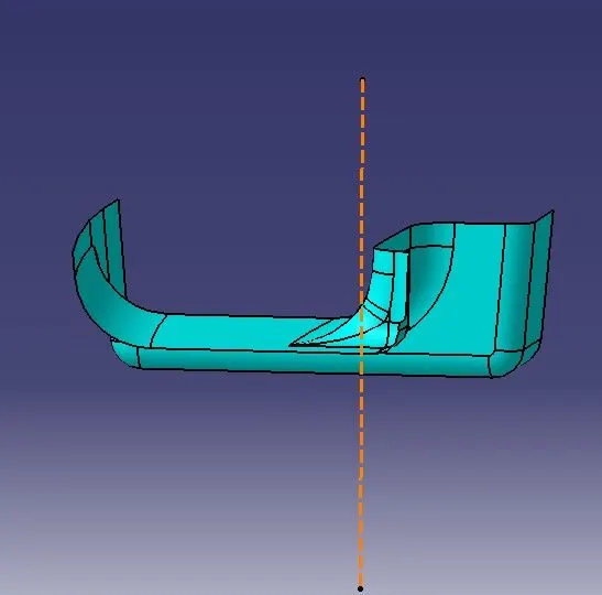
- Creating tooling axis.
- Tooling axis is created using a reference point created on the base surface
- Line is created normal to the base surface as it is horizontal to the plane parallel technique can be used.
- The dashed orange line shown in figure is the tooling axis.
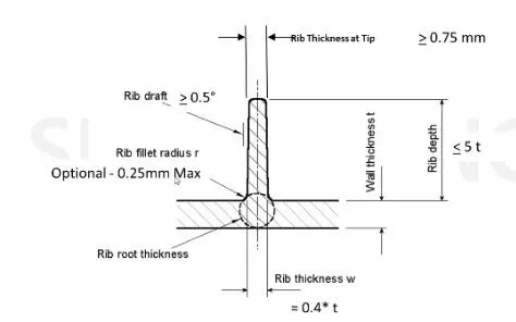
- Design rule for Ribs
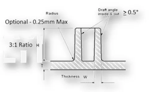
- Design rule for Screw boss
.
The procedure for draft analysis is as follows.
- From the Insert menu select Analysis option.
- Select Feature Draft Analysis.
- Select the Material option and drag the compass and place on tooling axis.
- Click on the surface.
- Make sure that the top surface is in green colour and click on OK .
Following are the results obtained by doing draft analysis
- Class A+B+C surface
For class A+B+C surface the draft angle provided is 3 degree.So,draft analysis is performed with 2.9 degree as draft angle.If all area is green colored then draft analysis passed as per given condition
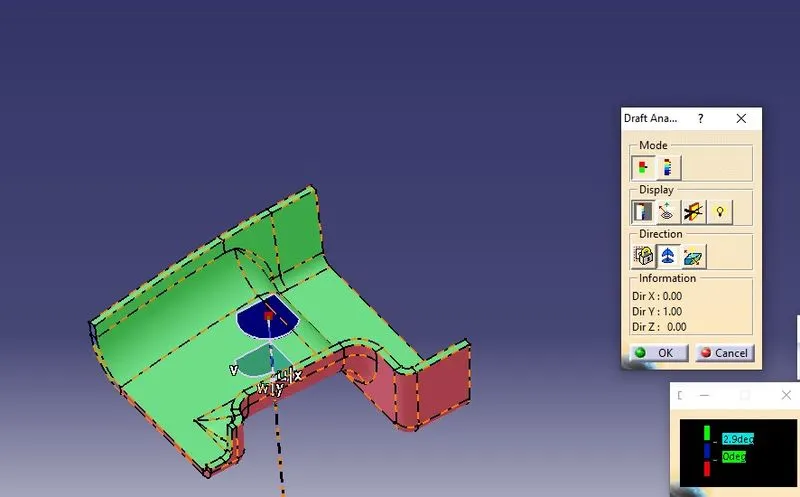
- Ribs and screw boss
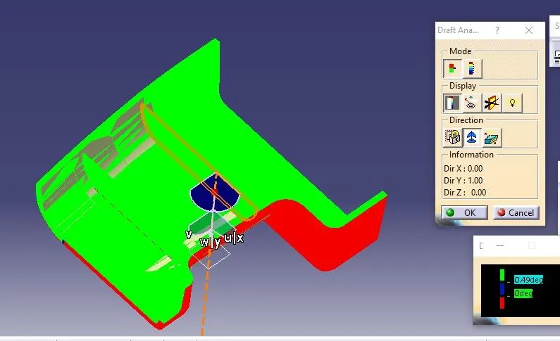
For ribs and screw bosses the draft angle provided is 0.5 degree.Draft analysis is performed with 0.49degree as draft angle.
- Draft analysis of Ribs
- Draft analysis of Screw boss
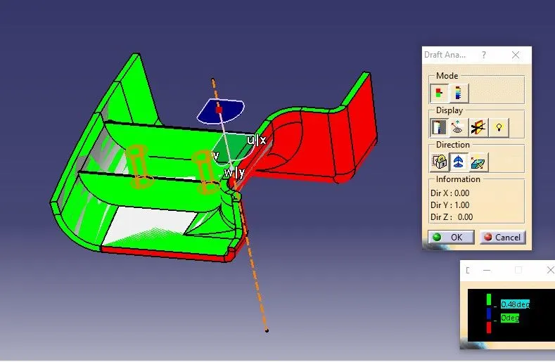
If all area is green coloured the draft analysis passed as per given condition.
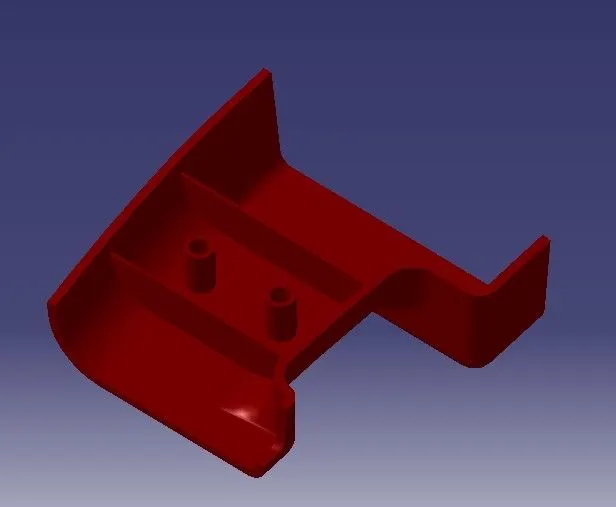
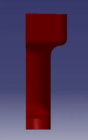
Following screenshots of the completed design in various orientations as follows
Isometric View
Front View
Side View
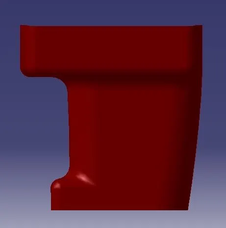
Top View
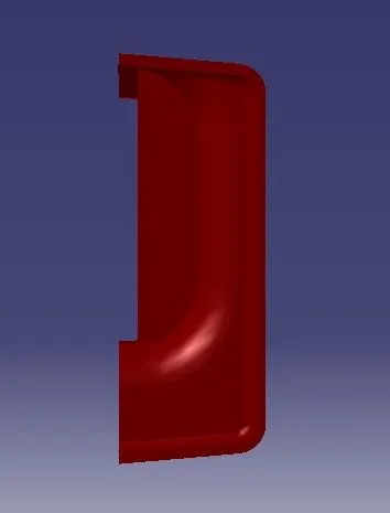
Tree Structure
Fully Defined Sketch
Conclusion:
Final output “Ribs and Screw Boss for Door Handle” is successfully designed using CATIA VS tool.