Week 9 - Attachment Feature Creation (Ribs & Screw Boss) - Challenge 1
RIBS CREATION
AIM: To design ribs on the coin holder considering every RIB design rule in the industry.
THEORY:
Class-B surface contains all the engineer data required for the model to be completed. Some of the major features of the B-side are:
- Ribs
- Screw boss design
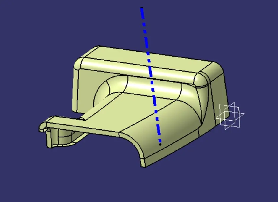
DRAFT ANALYSIS
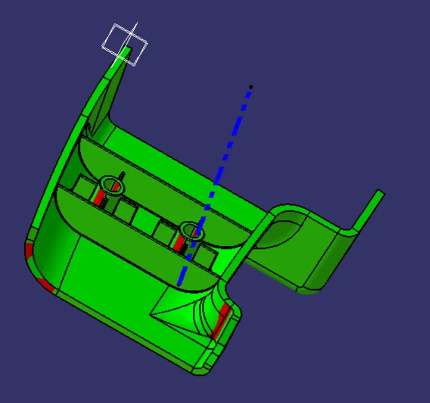
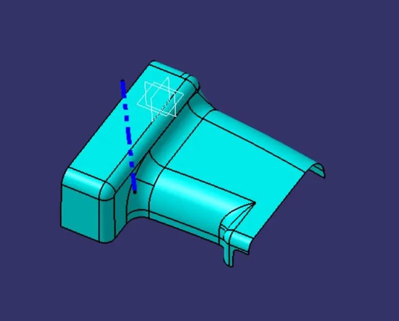
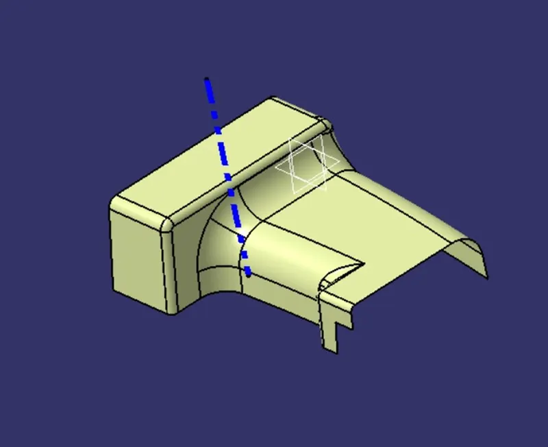
Draft analysis is a method used in design to check whether the component created in CAD is manufacturable based on the draft condition applied. The main reason behind the draft analysis is the part manufactured should be easily removed from the mold. It also gives an idea of the draft angle from the tooling direction. Here we are giving a tooling direction in order to eject the component easily from the tool. The ideal draft angle given in automotive industries for plastic components is 3 degrees.Some of the components where draft analysis is done are hood, fenders, roof, side doors, etc.
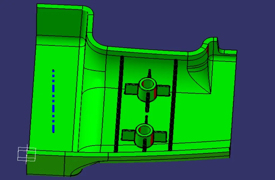
The draft analysis is an important tool as it helps the user to analyze the draft on various surfaces, the draft analysis in CATIA uses the color codes for the identification of the draft. Each color has its own meaning for the minimum draft negative draft and under draft.
The draft analysis toolbar provides two modes for analysis of the draft, first is the quick analysis which basically has three colors for analyzing GREEN, RED, AND BLUE on the other hand other option is the full analysis mode which enables a few more details into the draft and is used in the complex components like the instrument panel, etc. In the above challenge, we have used the quick analysis made for analyzing the draft here. Now, bring the compass and align it with the tooling axis and click the lock button in the dialog box.
RIBS:
They increase the stiffness and strength without increasing overall wall thickness of the model which is not desired. They also facilitate as Locator and arrest components of an assembly. Providing alignment in mating parts and acting as stopper or guides for mechanisms.
DESIGN RULES FOR RIBS:
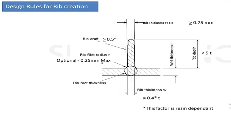
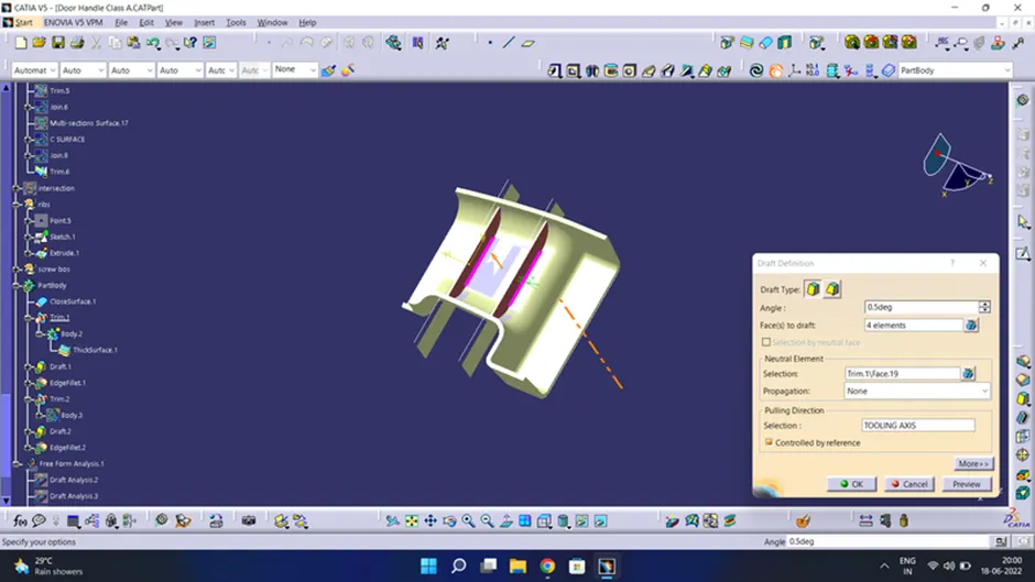
- Draft: 0.5 deg per side (minimum), but this value should not be high enough that it will cause failure for other consideration.
- Thickness of ribs: 40% of wall thickness
- Height: ≤ 5 times the wall thickness
- Spacing (for more than 1 rib): 3:1- steel height/width ratio (maximum). h/w =3or2(preferred) where h is the height of the rib and w is the space between two ribs.
- Minimum thickness at the tip: 0.75
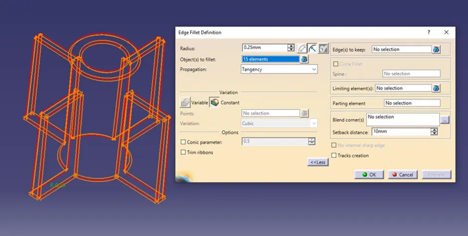
- Radius: 0.25mm max
- Ribs on opposite side of the wall should be offset
- Ribs should be connected to other structural features where possible.
- Rib root thickness should not be more than 30% of the wall thickness.
APPROACH:
Ribs are thin wall protrusions that extend perpendicularly from a wall or plane. They are usually found in clusters offering support to a plane that would have otherwise been too thick, but can also be stand-alone support for a single wall. They are commonly used to provide additional support and strength to a part. Thickness and location are essential to rib design.
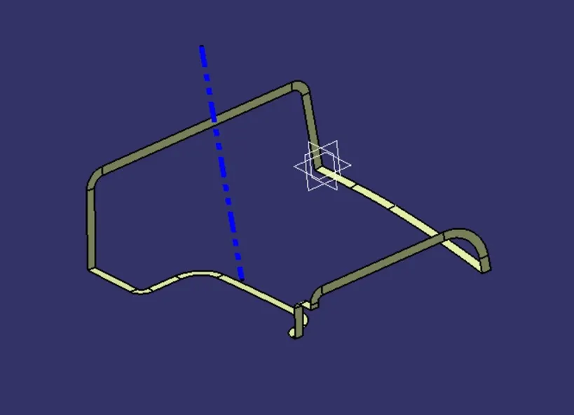
First, the base surface where the rib has to be created is extracted using the Extract command. A positioned sketch is created and the profile for the rib is drawn.
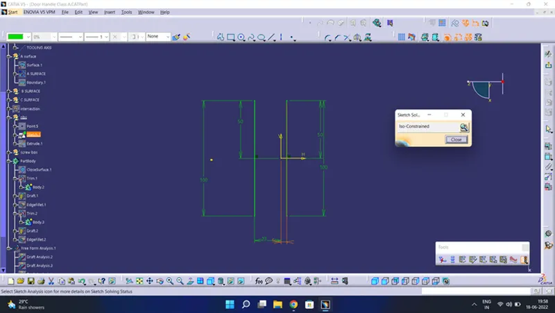
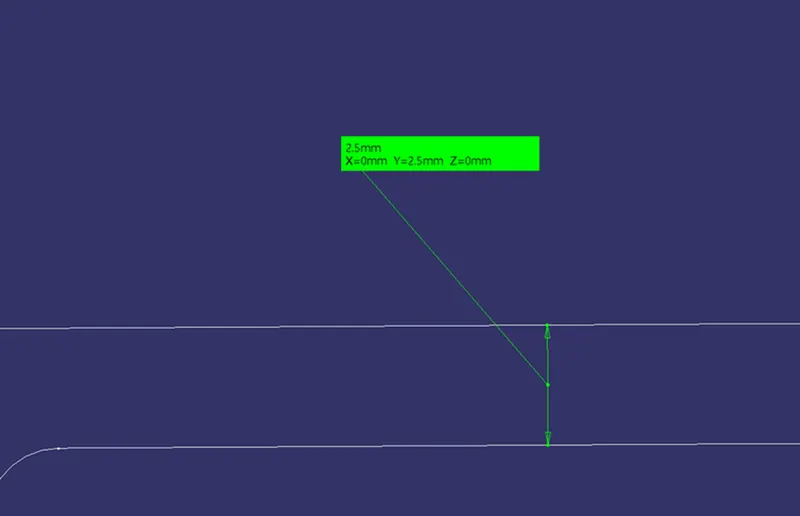
Next, the profile is extruded, to find the height, h=Wall thickness * 5
=2.5*5
= 12.5 mm
Therefore, the height is 12.5 mm
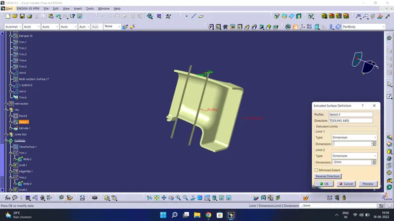
The extruded surface is thickened,
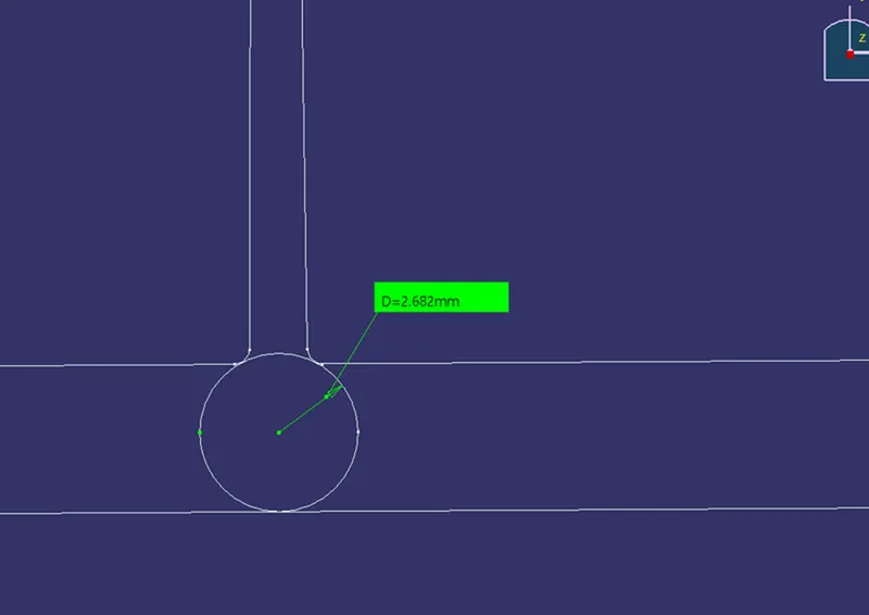
Thickness, w=0.4*t
=0.4*2.5
=1mm
SCREW BOSS
AIM:
To create a screw boss on a coin holder and preform draft analysis on it.
PROCEDURE:
Firstly, open the model using the open command.
SCREW BOSE:
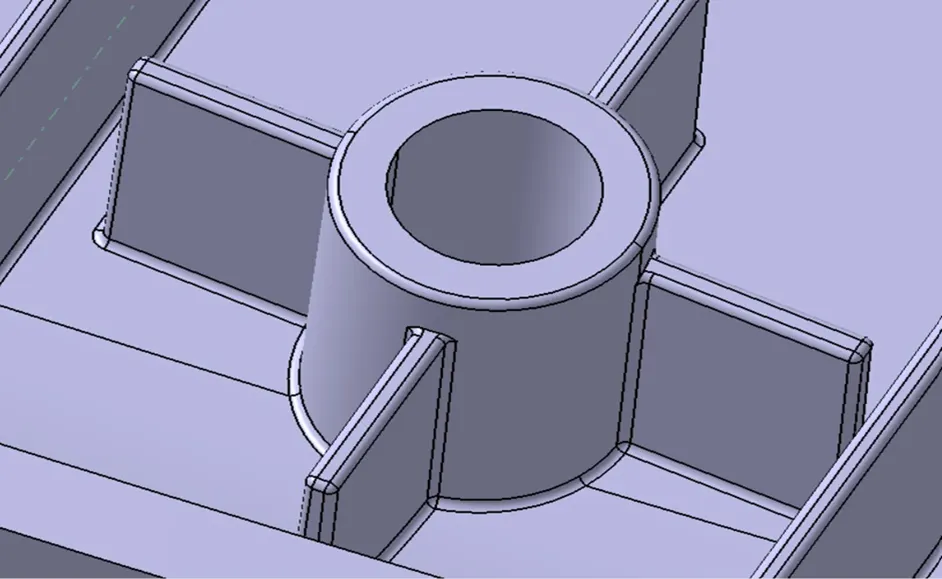
To create a screw boss, first, create a sketch and Iso-constraint it.
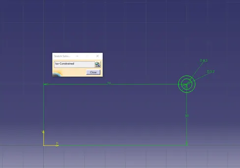
Pad the sketch to a height of 15mm as per 3:1 ratio.
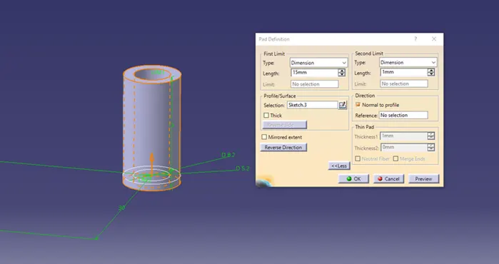
Then draft it with a min of 0.5 deg both inside and outside.
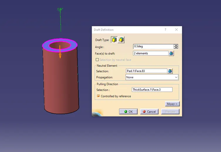
The boss is created but needs some support. So, we created ribs for support.
First, draw a sketch and Iso-constraint it.
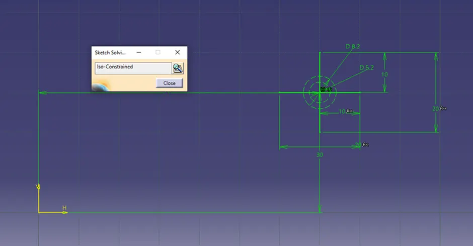
Now pad the ribs to a height of 12mm and second limit to 1mm select it as neutral element.
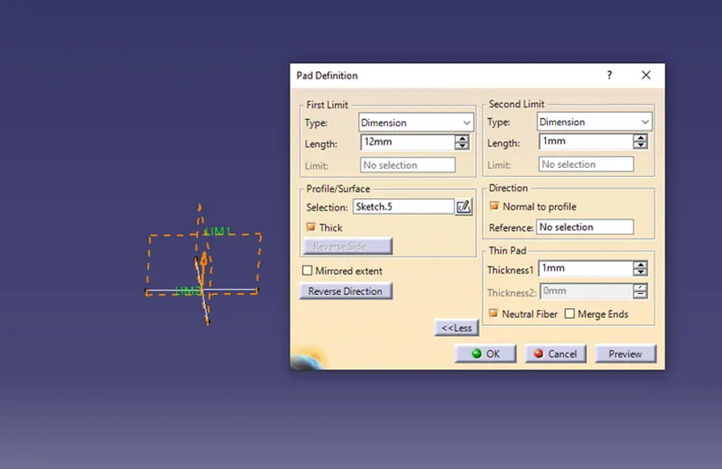
Now the ribs are drafted to 0.5 deg angle all sides.
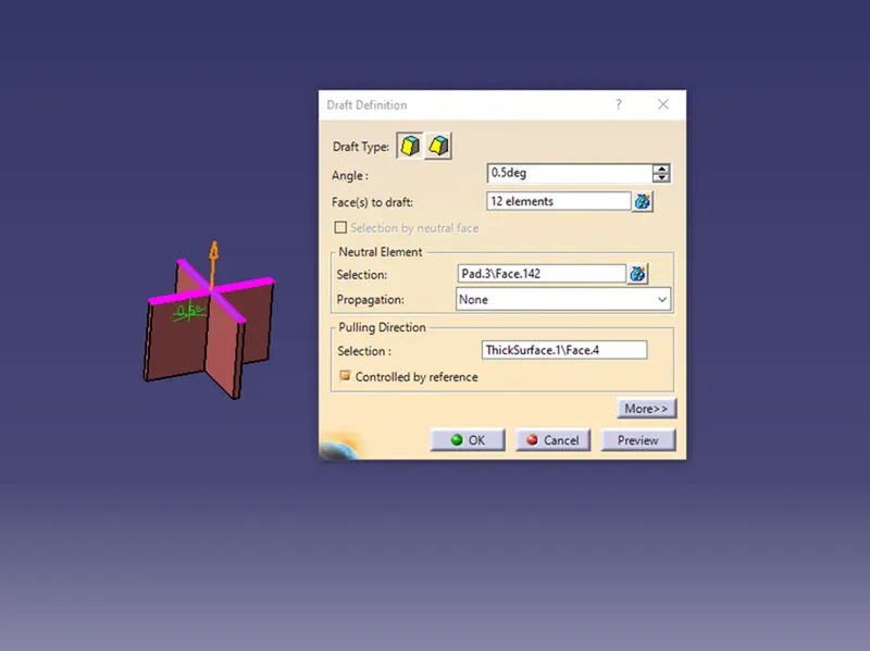
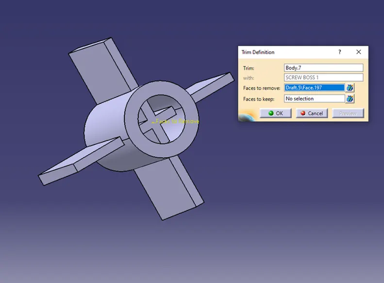
Trim the screw boss with the ribs.
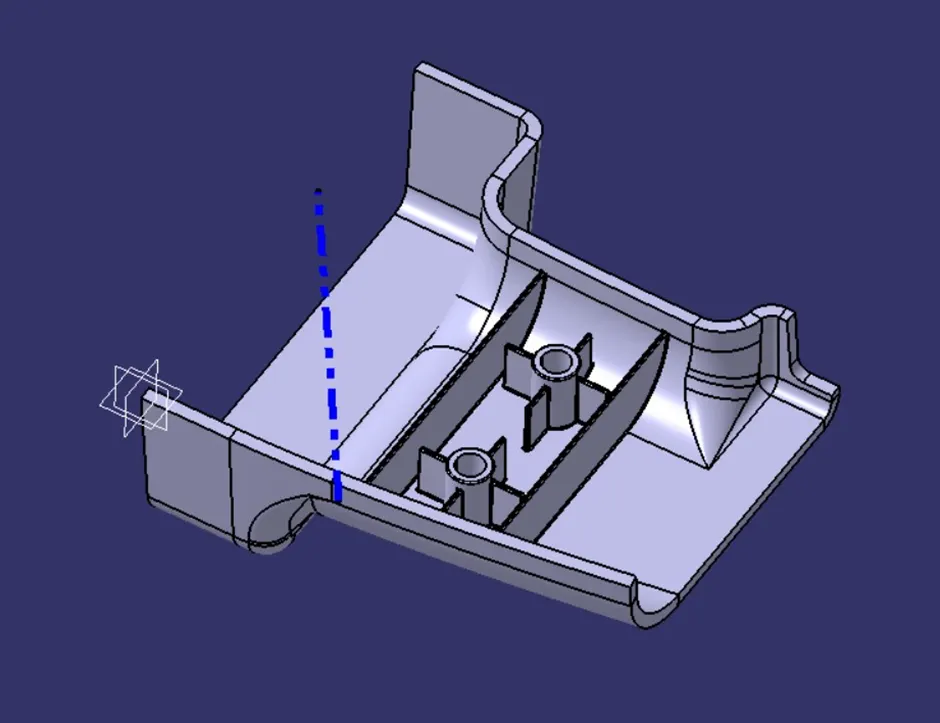
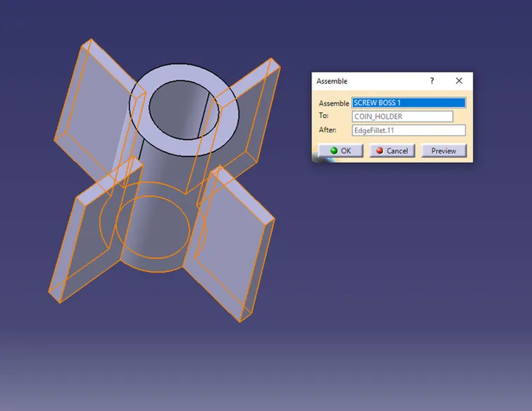
Assemble the screw boss with the coin holder.
Now give edge fillets to the edges of about 0.25mm.
The screw boss with ribs is attached with the door handle.
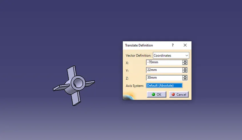
Similarly, to create another one copy the screw boss and past it in main part body then translate it.