Radar Mast & Final Assembly of Yacht
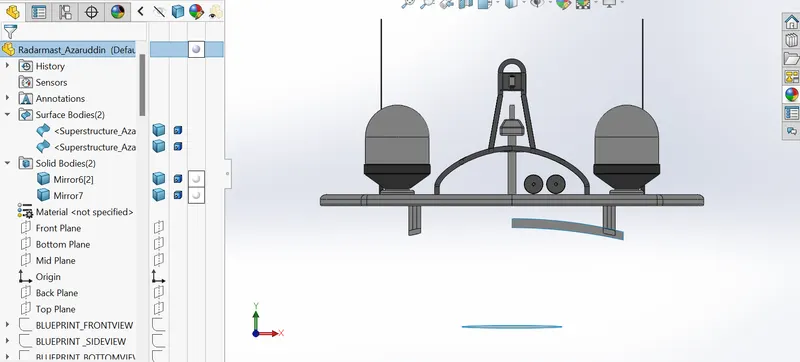
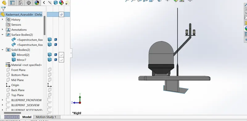
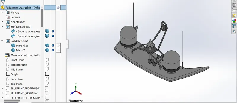
Radarmast
Front
Side
Isometric
Fully expanded view of feature tree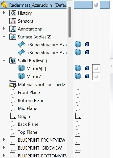
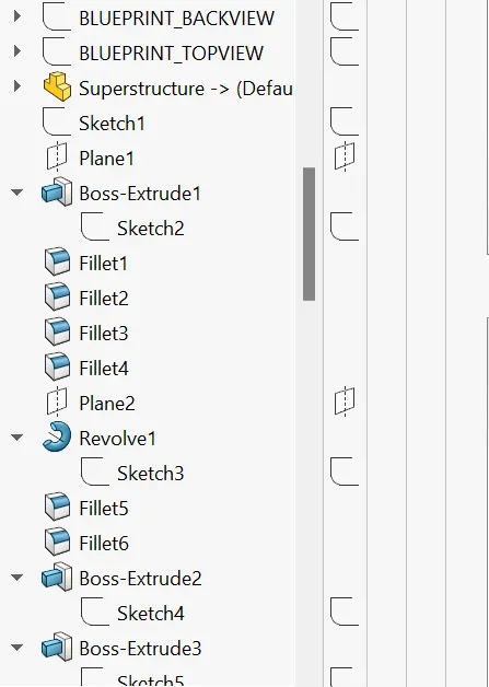
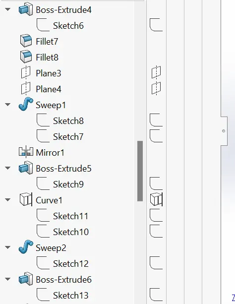
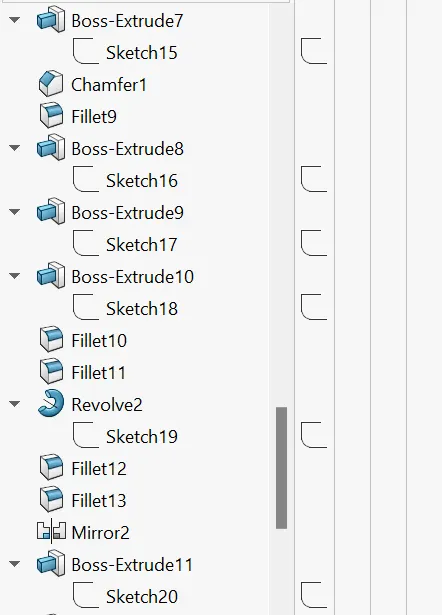
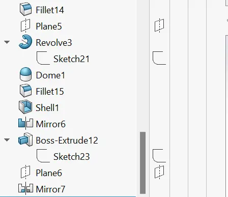
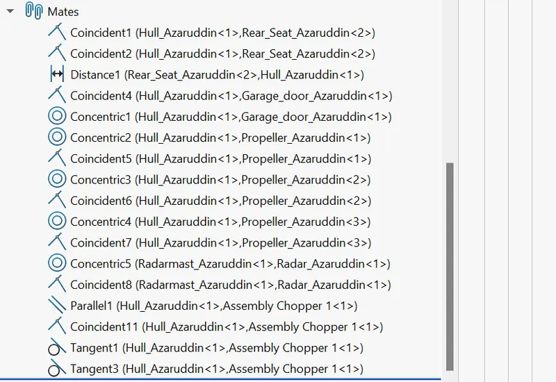
Assembly of Yacht
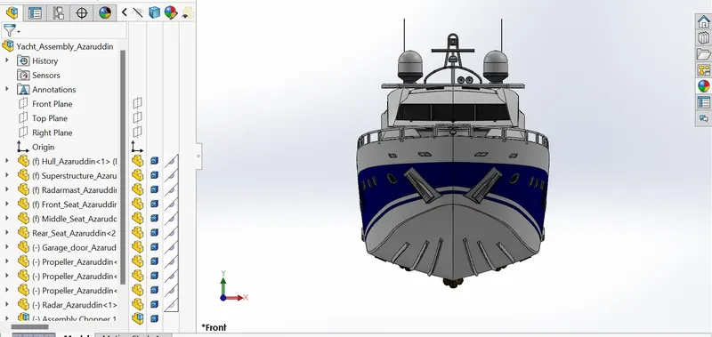
Front
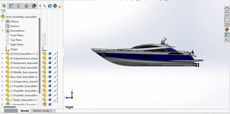
Side
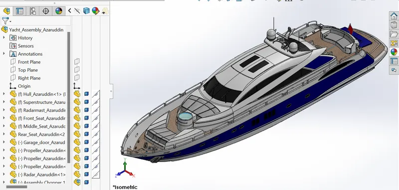
Isometric
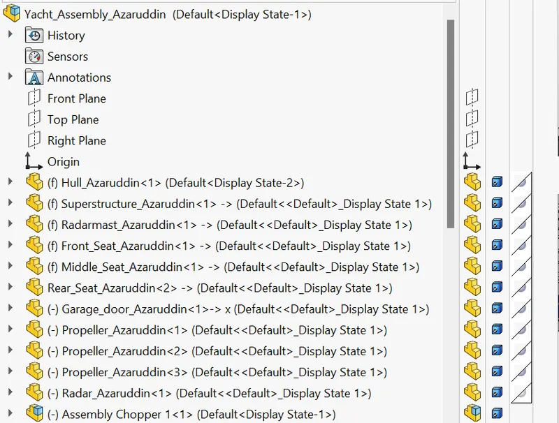
Fully expanded view of feature tree
YACHT REPORT
3D MODELLING OF YACHT
OBJECTIVE
The objective is to utilize and understand the tools and features available in the SolidWorks software to model the Yacht assembly.
Tools used are;
2D drafting
3D Solid Modelling
Surface Modelling
Assembly
Photo view 360 rendering
Features used are;
Sketching tools for drafting as line, circle, polygon, curves etc.
3D Solid modelling tools such as extruded boss, extruded cut, sweep, loft, revolve, helix, projected curves, etc.
Surface modelling tools such as surface extrude, surface loft, swept surface, trim surface, extrude surface, etc.
Assembly mating tools such as coincident, parallel, concentric, tangent, limit angles, etc.
Rendering tools such as adding decals, appearances, materials, background scene, camera settings, light settings, etc.
INTRODUCTION
The SOLIDWORKS CAD software is a mechanical design automation application that lets designers quickly sketch out ideas, experiment with features and dimensions, and produce models and detailed drawings. This document discusses concepts and terminology used throughout the SOLIDWORKS application. It familiarizes you with the commonly used functions of SOLIDWORKS.
DESIGN METHODOLOGY
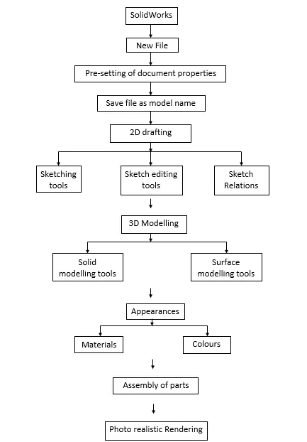
TOOLS AND FEATURES USED WHILE DESIGNING
To start with we first inserted all the blueprints of the hull in the workspace using sketch picture option such as front view, back view, side view, top view and bottom view. After inserting each view of blueprint, we placed it at a correct position by giving appropriate dimensions from origin and scaled it to the proper size.
PROPELLER
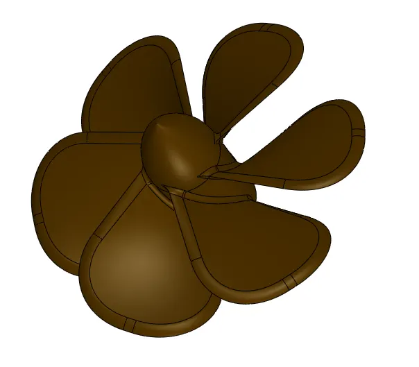
To model this, we first made the sketch for the axle. We drew c/s of the axle and then revolved it around central axis. Then for the blades we used lofted boss command using two sketches of the blade c/s. For the twisted profile of the blade, we drew the two c/s at different angles from each other which then lofting made them to follow the twisted path. Then we filleted out the corners to make it round. Then we made a hole cut out in the axle and again filleted out sharp edges. Lastly, we used circular pattern to copy all the blades in the circular direction.
Appearance: Coloured
RADAR
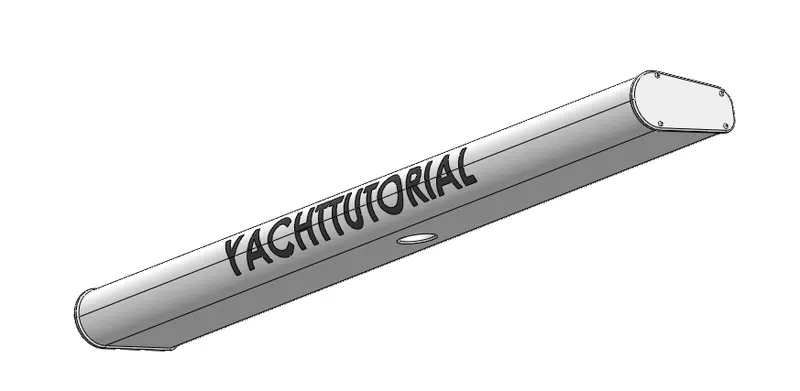
To model this, we first sketched the c/s of the radar and extruded it. Then we rounded all the four edges using fillet command. Then we took sketch on side surface and made offset of all the edges and extruded to some distance. Then for the nuts we used extrude boss and fillet command and then took the cut out of hexagonal shape using extrude cut. After that we used sketch driven pattern to copy the nuts at four different locations. Then we made a replica of our model using mirror command. For mid hole we used extrude cut. Lastly, we inserted a text on the surface of the radar using text command.
Appearance: Coloured
HULL
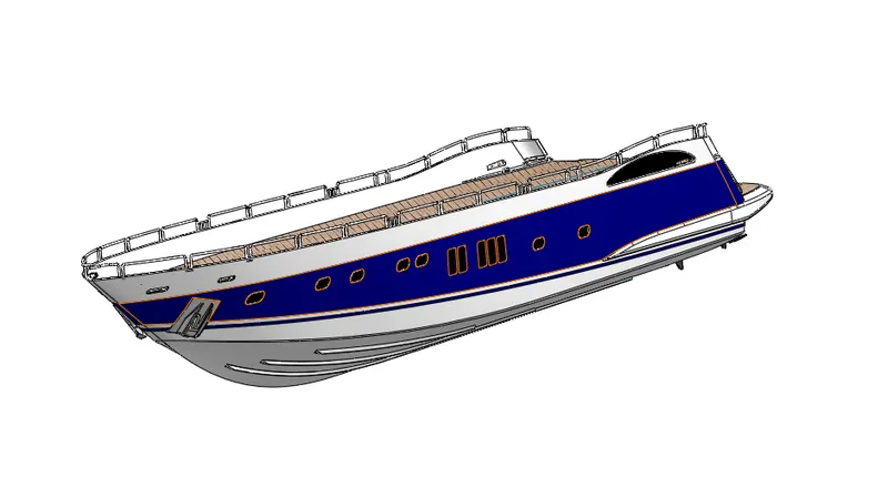
Hull is the watertight part of the Yacht which is partially submerged in the sea.
To model this, we used most of the surface modelling tools. We used lofted surface to create side surface of the hull. To do this we used four sketches two were projected curves and two normal splines. Also, for the surface below upper surface we used surface loft command where we used four curves and also kept the surface constraint as tangency to face and normal to profile.
Then we used surface fill to fill the upper surface and also used the trim surface command to trim off the extra surface entities. To fill out all the gaps between the edges of the surfaces we used surface knit command and also solidified the model. Then we used shell command to make the surface hollow but to have some thickness. Likewise, we used most of the solid and surface modelling tools to model this part.
Appearance: Coloured
GARAGE DOOR
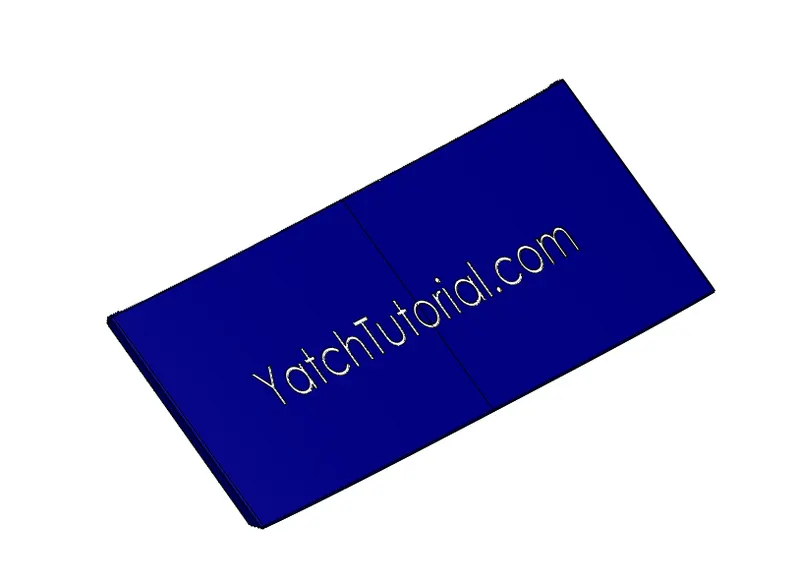
To model this, we used the part model from the hull file which was saved as a separate file. To make it as a garage door we first cut out the extra part to make it as a flat door using extruded cut. After that we used shell feature to take out some of the extra material and then used filler command to round off the edges. Then we made a hole at the side face to which will be used to hinge the door to the hull. After that we mirrored the entire body and inserted a text on the front surface.
Appearance: Coloured
FRONT SEAT
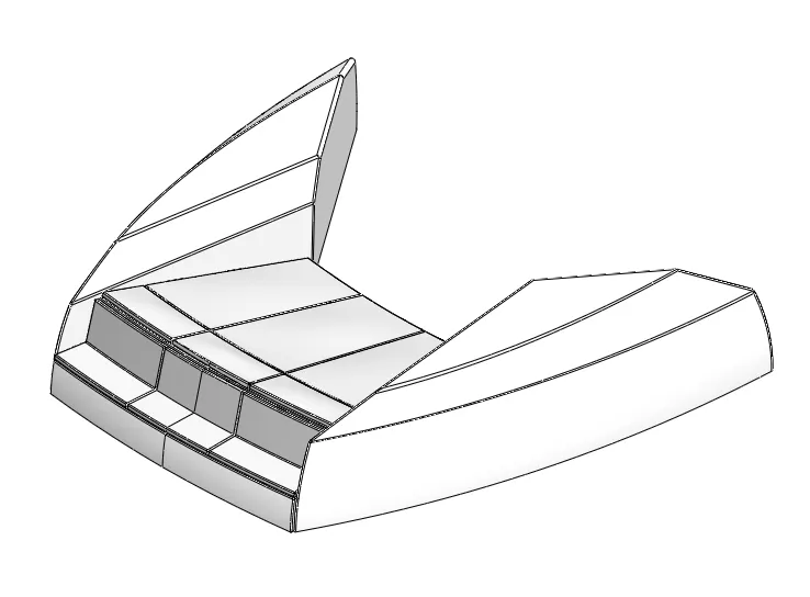
Front seat is the part of the yacht which is placed in front of the superstructure and on top of the hull.
To model this, we first inserted the hull body modelled previously and in the insert option we unchecked all the options except surface bodies which in turn inserted the offset surface of the hull top part. Using this surface as a base we modelled the front seat.
To model this, we used most if the surface modelling features as surface sweet, surface trim, surface fill, surface extrude, surface knit, offset surface and some solid modelling features ad extrude boss, cut extrude, chamfer fillet, revolve, mirror.
Appearance: Coloured
MIDDLE SEAT
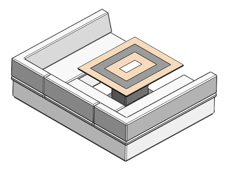
Again, to model this we used the surface created on to the hull body which we inserted to the workspace and used it as a base.
To model this, we used solid modelling features such as extrude boss, extrude cut, chamfer, fillet, mirror, etc.
Appearances: Coloured
REAR SEAT
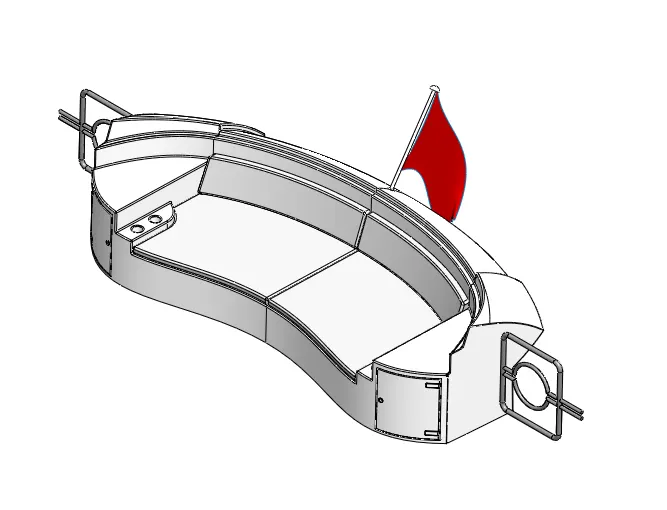
To model this last seat which is placed at the rear side of the hull behind the superstructure again we used the surface created on the hull.
To model this, we used most of the surface modelling features such as surface loft, surface sweep, surface extrude, extend surface, offset surface, trim surface, knit surface and some solid modelling features such as extrude boss, cut extrude, sweep, chamfer, fillet, etc and also used 3d sketching to model flag.
Appearance: Coloured
SUPERSTRUCTURE
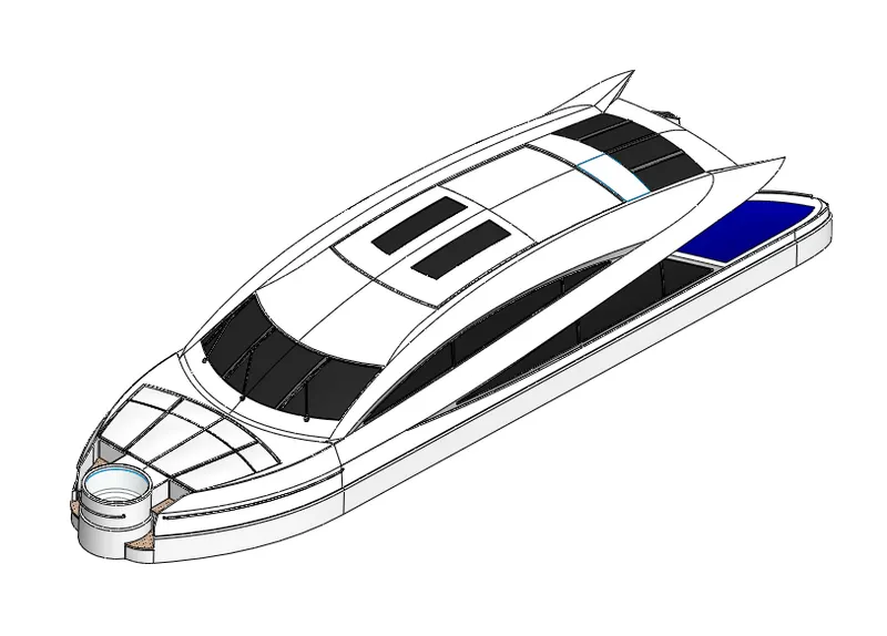
Superstructure is the largest body part which is placed on to the hull.
To model this, we used almost every feature of the surface modelling and solid modelling.
We used features such as surface sweep, surface extrude, surface extend to create the walls of the superstructure.
We also used surface loft, surface fill, boundary surface to fill the enclosed area between surfaces or sketches with the correct profile as we needed to match the blueprint.
We used surface trim feature to cut out the extra part of the surfaces which are not required and to give a proper shape as per the blueprint to the already created surfaces.
Then we used knit surfaces to knit all the surfaces together which takes out all the gaps present in between the surfaces and solidified it.
Solid modelling features that we used here are extrude boss, cut, sweep, revolve, fillet, chamfer, combine, etc.
Appearance: Coloured
RADARMAST
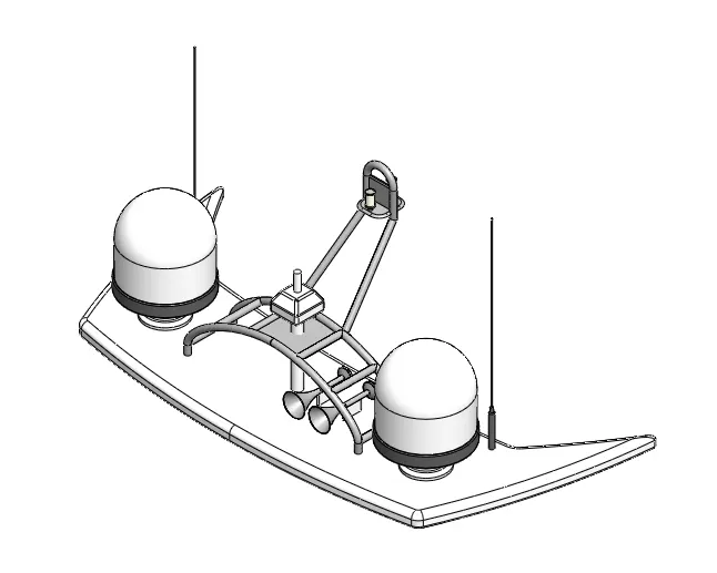
Radar mast is placed on top of the superstructure which is modelled using the surface created on the superstructure as a base.
To model this, we used most of the solid modelling features such as extruded boss, extruded cut, revolve, sweep, mirror, fillet, chamfer, combine, mirror, etc.
Appearance: Coloured
ASSEMBLY
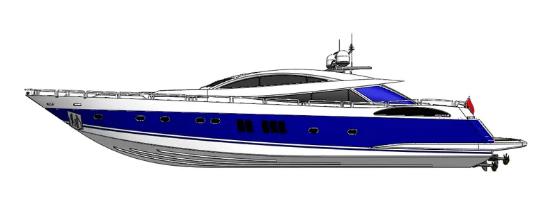
Front View
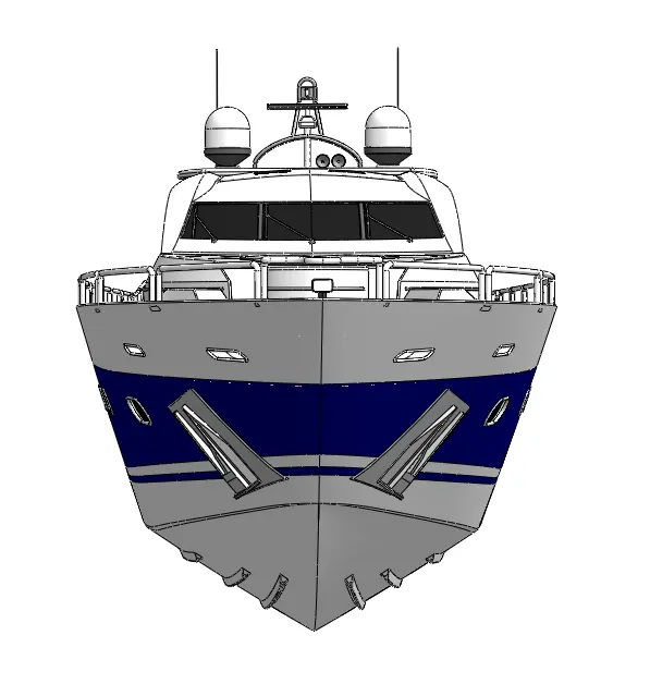
Side View
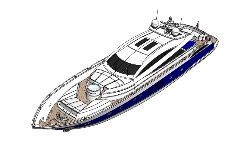
Isometric View
Camera Setup View 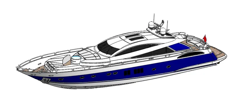
Top View
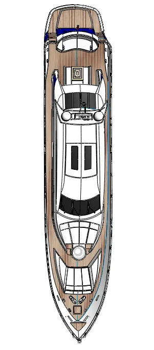
To assemble all the parts of the Yacht we first inserted the hull in to the workspace which got automatically fixed to the position.
Then we inserted superstructure, radarmast, front seat, middle seat which after got placed to the position automatically because we modelled it using the surface body of the hull at the correct position.
Then after that we inserted the rear seat which is placed using coincident and a distance mate. Then fixed it using the coincident mate between the midplanes of the hull and the rear seat.
Now we inserted the garage door which is placed using coincident mate between its midplane and the hull’s midplane.
Then we used a concentric mate between the hole of the garage door and the shaft present on the hull body at the garage opening which made the door to hinge and enclose the garage space.
Then we inserted three propellers and used coincident and concentric mate relation between hole of the propeller and the shaft to all of them.
Then we inserted the radar to assemble it on the shaft of the radarmast. We used coincident and concentric mates between the hole in the radar and the shaft on to the radarmast.
Lastly, we inserted our chopper model to place it into the garage space. To place it we first used coincident mate between the midplanes of the chopper and the hull. Then we used a tangent mate between both the wheels of the chopper, kickstand and the garage floor. Then we dragged the chopper model into the garage.
PHOTO REALISTIC RENDERING
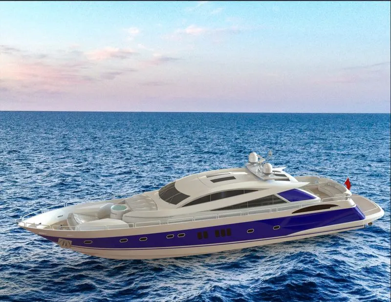
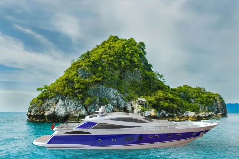

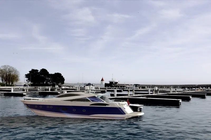
This tool is used to give a realistic feel to our model in the form of image.
To do this we first added some decals to some parts of Hull body and placed it on the surface by adjusting its size to correctly fit.
Then we selected appropriate background scene for our model which will look perfect fit according to our model. Then we set some settings such as render quality, bloom, background brightness, render brightness, scene reflectivity, etc.
Then we set our model for it look standing on the ground using floor offset. Then we set some lights and camera. In the camera we set some field of view where we adjusted the screen until we got the appropriate view and added some depth of field which gave us the focused view for it to look more realistic.
Lastly, we checked our render using render preview for the quality and if our model is blended in the background environment properly. And when everything looked fine, we created a final render image of it.
CONCLUSION
So, in the conclusion we can say that we have successfully studied, learned and applied all the Solid modelling, surface modelling and sketching tools of SolidWorks used to model this Body.
Also, we have understood the assembly tools required to assemble each part of the body using proper mate relations to make a complete assembly.
And lastly, we have also understood and utilized rendering tools to make a realistic image of our model. So, we can say that SolidWorks is an excellent software using which we can visualize, model and edit any kind of part quickly using large variety of features present in the software.