Photo Realistic Rendering
3D MODELLING OF AMERICAN CHOPPER
OBJECTIVE
The objective is to utilize and understand the tools and features available in the SolidWorks software to model the American Chopper assembly.
Tools used are;
2D drafting
3D Modelling
Assembly
Photo view 360 rendering
Features used are;
Sketching tools for drafting as line, circle, polygon, curves etc.
3D modelling tools such as extruded boss, extruded cut, sweep, loft, revolve, helix, projected curves, etc.
Assembly mating tools such as coincident, parallel, concentric, tangent, limit angles, etc.
Rendering tools such as adding decals, appearances, materials, background scene, camera settings, light settings, etc.
INTRODUCTION
The SOLIDWORKS CAD software is a mechanical design automation application that lets designers quickly sketch out ideas, experiment with features and dimensions, and produce models and detailed drawings. This document discusses concepts and terminology used throughout the SOLIDWORKS application. It familiarizes you with the commonly used functions of SOLIDWORKS.
DESIGN METHODOLOGY
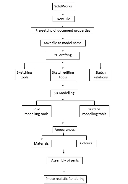
TOOLS AND FEATURES USED WHILE DESIGNING
TRANSMISSION BELT
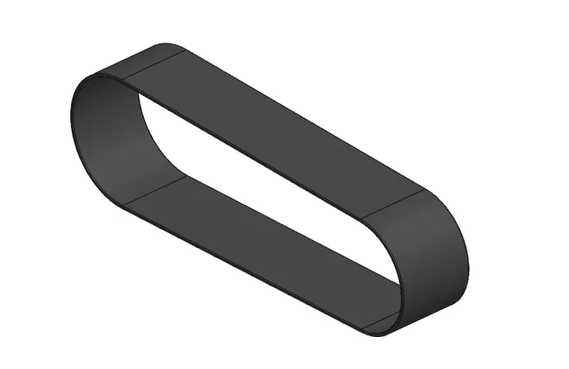
Transmission belt is a part of the engine which is used to transmit the motion of the motor to the intermediate gear.
To model this, we first sketched the side cross section of the belt using sketching tools such as line, circle and then offsetted the sketch to make a closed cross section which is then extruded to get a 3d model.
We have also added some sketch relations such as horizontal, tangent to make the sketch fully defined.
Material: Matte Rubber
KICKSTAND
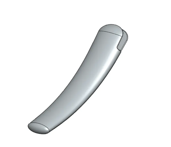
It is device which is attached to the lower portion of the chassis and it allows the bike to be kept upright without leaning against another object.
To model this, we sketched the ellipse for the cross section and a spline for the path and then again made one more elliptical c/s at the other end. Then we used loft operation to make a wedge shape and used dome command on the larger flat surface to make it swollen. After that we cut some sections and made one cylinder at the end to hinge the stand to the chassis.
Material: Chromium Plate
FRONT FENDER
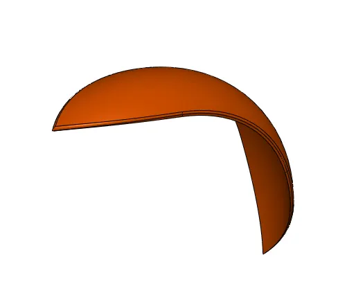
Front fender frames the front wheel of the bike to prevent the body from the sand or mud thrown by wheels.
To model this, we first sketched the c/s of the fender and then revolved it up to some appropriate degrees from both directions. For the pointed cone front end, we sketched a conical drawing and then later used it for split to cut feature to remove excess material and at the other end of the fender just rounded it. Lastly, we filleted out all the sharp edges.
Appearance: Siena Paint
REAR FENDER
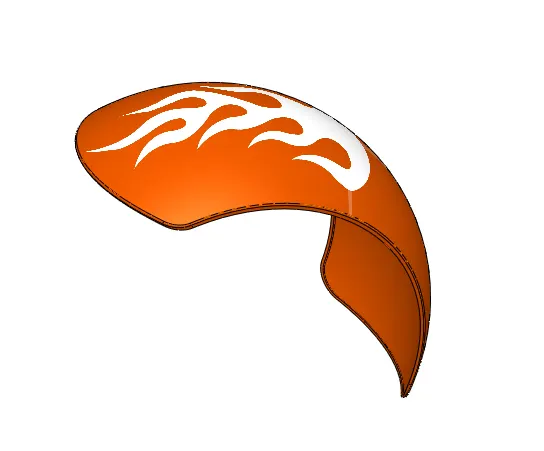
Rear fender frames the rear wheel of the bike to prevent the body from the sand or mud thrown by wheels.
To model this, we followed the same process as in front fender but in this we just had to make both the ends rounded. So, we did it using appropriate sketches and split cut feature and the other end rounded it using fillet feature. Then we used a shell feature to shell it inside surface of the fender for the wheel to fit inside. Lastly, filleted out all the sharp edges.
Appearance: Siena Paint
CHAIN
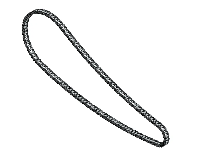
Chain is made by interlinking several links throughout its length which is used to transmit the power from the intermediate gear to the rear wheel.
To model this, first we sketched the chain path length and then the two links and made both the links as a block to use it several times afterwards. After that we inserted both the links and placed it in line with the path. Then extruded both chain links and linearly patterned it along the chain line up to the point the links are following the line. After that we followed the same process until all the links are pasted successfully following exactly the chainline and also added the pins in the holes at the each linking areas.
Lastly, mirrored all the chain links using midplane as the mirror plane.
Material: Chrome plate
OIL TANK
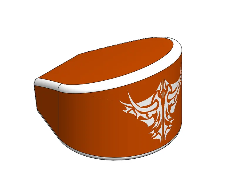
Oil tank is used to store the oil and it is rested on the engine casing.
To model this, we sketched the two different c/s viewed from front and side on the two different planes front plane and midplane respectively. Both the c/s made using appropriate sketches and appropriate dimensions for the model to fit it in between the chassis and the engine casing. After that we extruded both the sketches.
Later we used the combine command to take out the common intersecting part as a resultant body. Then filleted out all the sharp edges and used the shell command on whole body to make it hollow from the inside.
Appearances: Whole body – Siena paint
Fillet face – White colour
PEDAL
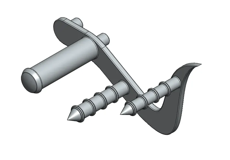
The pedal is the part of a bike which is used to rest the feet while riding.
To model this, we first modelled the hook shaped design of the pedal. For which we used appropriate sketches and dimensions with all the possible relations to fully define it. Then extruded it.
After for this pedal plate to be fixed on the chassis we made two small cylindrical rods at the back which will be fixed in the holes made onto the chassis during the assembly. Later we made the two rods ate the front end for the foot rest. We used fillet and chamfer command to blunt the sharp edges and given the desired shape. At last, we made some cylindrical rings around the front-end rods for the grip. To model this used features are offset sketch, extruded boss and linear pattern.
Material: Chrome Plate
FRONT WHEEL
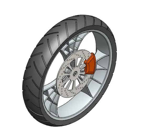
Front wheel is a part of the bike having spokes, axle, disc brake, rim, hub and the tire which in all together is responsible to guide the bike in the appropriate direction.
Rim & Hub:
To model this, we made the cross section of both rim and hub and revolved it around central axis.
Spider webbed spokes:
To model this, we first sketched a plate on the right plane on which the spider webbed cut out shall be made. After sketching we extruded it through midplane. Then we took a sketch on the surface of the plate and drawn a structure looking like spider web and then we took a cut out of the areas not required for the plate to look like a spider webbed spokes. Then we combined the spokes to the rim. After that c/s of the spoke was larger than the rim. So, we just trimmed the excess areas using proper sketch and revolve cut to make a smooth transition between spokes and the rim. And lastly, we made a circular pattern of it.
Rotor:
For this we just drawn a circle and extruded it to make plate first. Then of the surface of it we sketched circle at desired location then used linear and circular pattern to get the design all around the plate.
Calliper:
This is modelled just by using some lines, circles, trim tool and extrude boss command. And also fillet and chamfer to blunt the edges.
Tire:
For this we just made a c/s of it over the rim and revolved it. Then we drawn some rectangular shapes at some angles for the tire grip and then using extruded cut we took out some areas. Lastly, we filleted some edges of grips to make it smooth and made a circular pattern.
Appearance and materials: Rim & spokes: Chrome plate
Rotor: Carbon Steel
Calliper: Siena Paint
Tire: Matte Rubber
REAR WHEEL
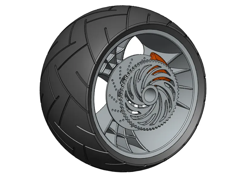
Rear wheel is a part of the bike which is used to drive the bike using the motion transferred by the engine.
To model this, we followed the same process as in the front wheel except we just added two more parts that are; Axle and Sprocket.
Axle:
For this we sketched c/s of it on the front plane and revolved it around the central axis.
Sprocket:
For this we followed the same steps used to model the rotor but using the different sketch design. We also made gear teeth on around the sprocket using appropriate sketch on the surface and then we cut out it and made a circular pattern of it.
Appearance and materials: Rim, Spokes, Axle & Sprocket: Chrome plate
Rotor: Carbon Steel
Calliper: Siena Paint
Tire: Matte Rubber
FRONT FORK
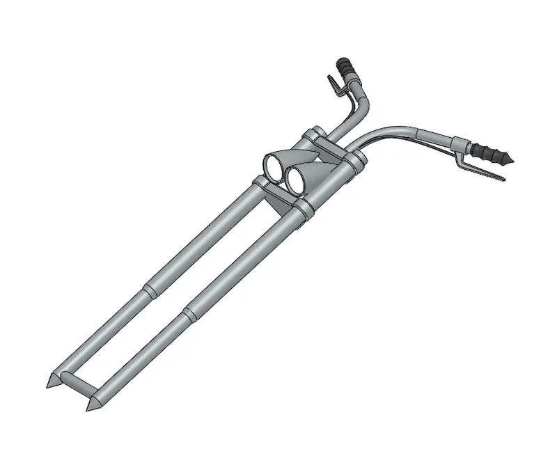
Front fork is that part of the bike which attaches the front wheel with the rest body.
Forks:
To model this, first we sketched the cross section of the rod and revolved it around. Then after, we drew the sketch for the clamps which are used to held the headlights in place and also join the rods from the top. Then extruded the clamp sketch and made the linear pattern of it at some distance for the second clamp. Then we extruded the rods through the clamps ahead of it and made one tube on the backside of the first clamp to join it horizontally to the other clamp.
Headlights:
To model this, we sketched the c/s and then revolved it around. Then we used Move/Copy command to move the model and made some operations on it such as cut extrude using draft for light area, fillets and dome.
Handle:
To model this, we used sweep operation for which we made circle as a c/s and for the guiding path we used a projected curve. For projected curve we made two reference sketches which are used to project the resultant curve.
Handle grips:
To model this, we first made a perpendicular reference plane on the end surface of the handle and made the sketch of the gripper c/s and revolved it.
Brake lever:
In this we first modelled the brake lever fixture through which the handle is passing. For this we made c/s sketch on previous plane and revolved it. Then we created new plane on reference to previous one at some angle and made the brake lever sketch and extruded it. Lastly, applied some fillets.
Brake wire:
To make the wire we used sweep command. For the geometry we made circle on the lever and for the path we used projected curve using two different reference curve sketches.
Appearance and materials: Entire part: Polished chrome
Handle grips: Glossy Rubber
Headlight: Area light
CHASSIS
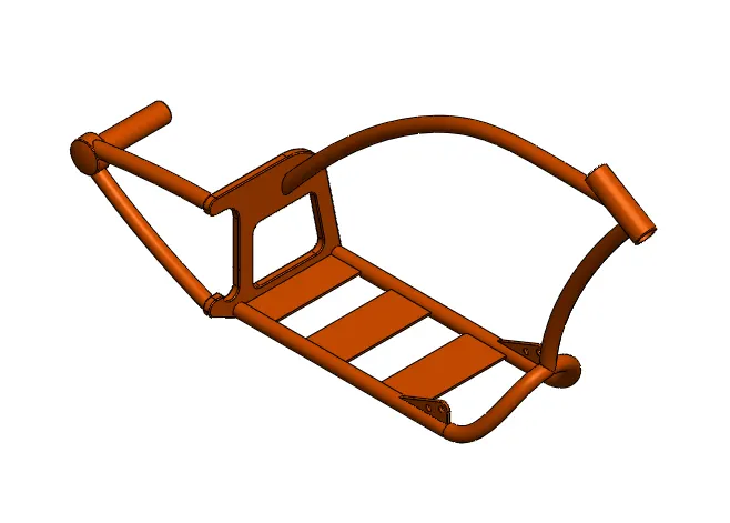
Chassis is that part of the bike which encloses the whole body and attaches and holds every part together.
Firstly, we added a sketch picture of the chassis to use it as a reference to model this part.
To model this, we used commands such as sweep, projected curves, split cut, extrude boss, extrude cut, combine, mirror, revolve, reference planes, fillet, chamfer etc.
To model all the tubes required in the body we used sweep command with c/s and projected curves as a guiding curve to follow. Projected curves are made using two different sketches.
The head tube is modelled using revolve command. Then whichever tubes or parts are intersecting into each other are cutted out using split cut command. The cut outed piece is a part of that body whose intersection was not required.
We used the mirror command to make it symmetrical from both sides and combined the whole body to make it as a one single part.
We used the reference planes wherever we required the sketches to be drawn at some distance or angles from the standard planes or the faces of the body parts.
We used the extruded boss and cut command to make 3d solid parts of the required shape and size.
And lastly, the chamfer and fillets are used to blunt the sharp edges or to make them a bit smoother.
Appearance and materials: Siena paint
ENGINE
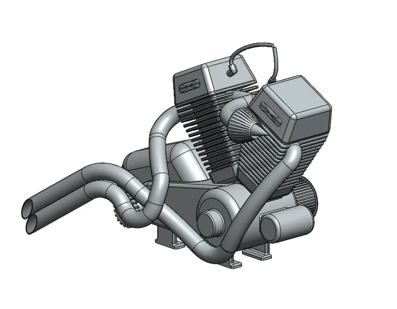
Engine is the main part of the bike which is used to drive the wheels which in turn moves the bike.
First, we added a blueprint of the engine to use it as a reference to model this part. To model this, we used commands such as extrude boss, cut, sweep, projected curves, split cut, linear and circular pattern, combine, mirror, revolve, reference planes, fillet, chamfer and some sketching tools such as line, circle, splines, rectangles, offset entities, convert entities, sketch relations, etc.
Extrude boss and cut is used to model the bottom casing of the engine, two rotors, two upper cylinder casing and the four base pillars on which the engine will stand.
Sweep command is used to model the gas wires coming from gas tank to the engine, exhaust manifold, etc using appropriate sketches and paths.
Projected curves are used to make the paths for the sweep operation using two different reference sketches.
Linear pattern is used to make the fins over the cylinder casing and circular pattern is used to make the tooth on the intermediate gear and some holes on the two rotors.
Mirror tools is used to duplicate the part and combine is used to join the two parts into single.
Lastly, fillet and chamfer tool is used to smooth the sharp edges wherever required.
All the modelling tools are used over the 2d sketches which are drawn using appropriate sketching tools and relations.
Material: Chrome plate
GAS TANK
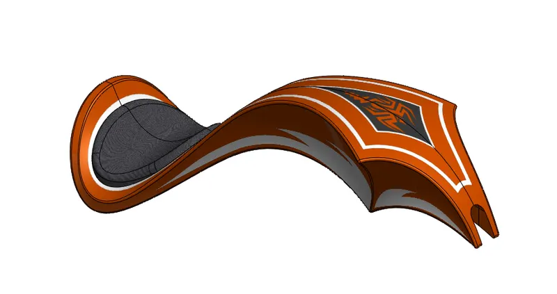
Gas tank is used to store the fuel to run the bike whose body encloses the chassis form above and also has a seat attached to it.
First, we added a sketch picture of a fuel tank to use it as a reference.
To model this, we used surface modelling tools, solid modelling tools & sketch tools. We used surface sweep, surface loft, surface extrude, boundary surface, surface trim, fillet, split line, knit surface, swept cut, projected curves, reference planes, etc.
Use of features to create the geometry:
Surface sweep is used to create the upper surface of the gas tank using two curves, one for geometry and another for path. Then we trimmed the excess surface using trim surface command to give it a perfect shape from the sides.
Surface loft is used to create the side face present at the front of the tank using one edge, one curve and one projected curve.
Boundary surface is used to create the second side surface using one edge and a projected curve as a first direction boundary reference and the two straight lines at the end and middle and one edge curve as another direction boundary reference.
Mirror is used to replicate the half body and knit surface is used to fill out if any gaps present at the edges of the engaging surfaces.
Swept cut is used to make a half groove at the bottom surface of the tank for the tank to be placed correctly on the upper surface of the chassis without intersecting surfaces of both the parts into each other.
Split line is used to separate the surface for the seat using creating a sketch on the bottom plane, which is then extruded using surface extrude to make it a solid body.
Lastly, we used fillet to blunt all the sharp edges and to make smooth transition at the edges and created a shell of the whole gas tank using shell command.
Appearance and materials: Body: Siena paint
Seat: Grey cotton fabric
ASSEMBLY
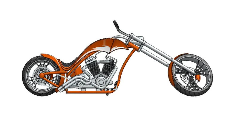
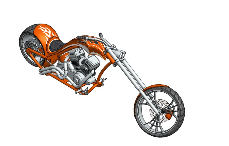
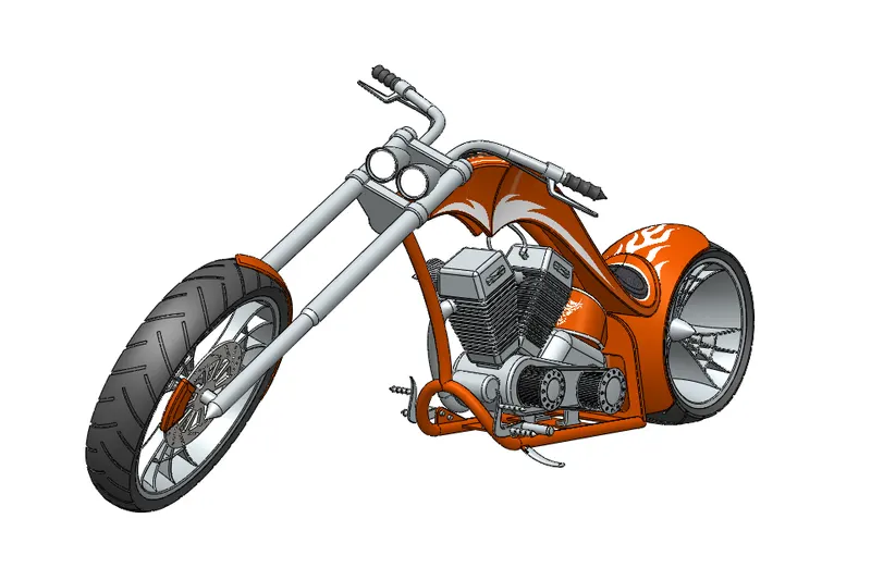
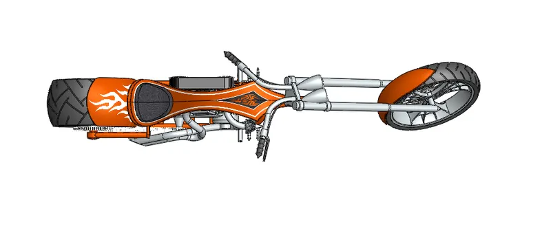
Front view Side view Isometric view
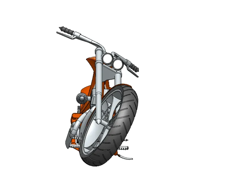
Camera Setup view Top view
Assembly is a tool of SolidWorks which is used to assemble all the parts to make one single device.
To do this there are features like move, rotate, mate, etc to place every component at its desired location with appropriate mate relations.
First, we inserted chassis in the assembly and kept it at some position. Then we inserted engine. To place it at correct location we used coincident mate relations between some planes and some faces and also given a distance relation to place it exactly at the given location.
Then, we inserted pedal and gave it a concentric relation to the hole in the chassis and the rod in the pedal and a coincident relation between two faces to hinge it properly. Then we gave a limit angle relation to limit the movement of the pedal.
Now, we inserted kickstand into assembly. Here we gave two concentric relations to the two rods and the holes in the chassis where it is needed to be placed then lastly the coincident relation between two faces of placed it at the correct location.
Then, we inserted transmission belt to place it on the two rotors of the engine. To do this we used concentric and width relation to place it exactly in the gap present on the rotors. After that we used a limit angle relation to place the belt correctly.
Then to place the oil tank we used coincident relations between some planes and the faces of the oil tank, engine and chassis.
After that we inserted the rear wheel. To place it we gave a concentric relation between axle on the chassis and the central hole of the rear wheel. Then we gave coincident and parallel relations between the planes of the rear wheel and the chassis which attached it to the chassis at the correct location.
Then, we inserted rear fender where we used coincident, concentric and a parallel mate to place it on the wheel.
Now we inserted the chain to place it on the intermediate gear and the sprocket of the rear wheel. To do this we used concentric, width and parallel mate.
Then, we inserted Gas tank where we used some distance relations between some planes and a coincident relation which placed it properly on the chassis.
Then we inserted front fork where we used concentric, limit angle and a width mate with the chassis.
Now we positioned the front wheel using some concentric and coincident relations with the front fork.
And lastly, we inserted front fender where we used some coincident relations with the front fork which placed it correctly to the position with which made the entire assembly fully defined.
Now to make the bike look real we had to make it stand on some plane. To do this we used tangent mate relation between contacting surfaces to the ground. So, the contacting surfaces were front wheel, rear wheel and pedal and the top plane is used as a ground surface.
PHOTO REALISTIC RENDERING
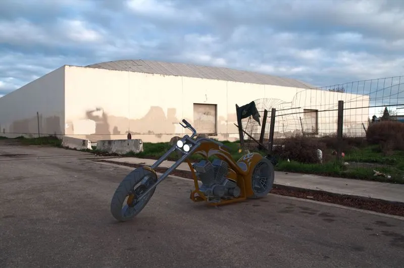
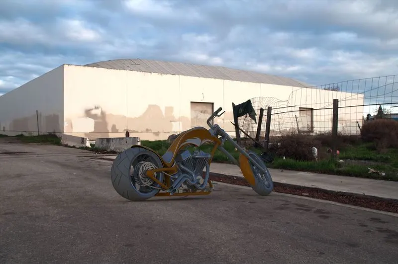
This tool is used to give a realistic feel to our model in the form of image.
To do this we first added some decals to some parts of our model as gas tank and oil tank and placed it on the surface by adjusting its size to correctly fit.
Then we selected appropriate background scene for our model which will look perfect fit according to our model. Then we set some settings such as render quality, bloom, background brightness, render brightness, scene reflectivity, etc.
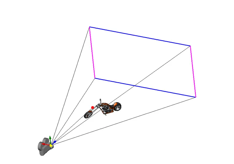
Then we set our model for it look standing on the ground using floor offset. Then we set some lights and camera. In the camera we set some field of view where we adjusted the screen until we got the appropriate view and added some depth of field which gave us the focused view for it to look more realistic.
Lastly, we checked our render using render preview for the quality and if our model is blended in the background environment properly. And when everything looked fine, we created a final render image of it.
CONCLUSION
So, in the conclusion we can say that we have successfully studied, learned and applied all the Solid modelling, surface modelling and sketching tools of SolidWorks used to model this Body.
Also, we have understood the assembly tools required to assemble each part of the body using proper mate relations to make a complete assembly.
And lastly, we have also understood and utilized rendering tools to make a realistic image of our model. So, we can say that SolidWorks is an excellent software using which we can visualize, model and edit any kind of part quickly using large variety of features present in the software.