Week 9 - Attachment Feature Creation - Challenge 2
Aim:
To create a door trim Plastic Component through a given Class A Surface and perform Draft Analysis on the final plastic component.
Objectives:
- To Create a Tooling Axis.
- To Create Class B and Class C surface.
- To Create a solid part using surface modelling.
- To Perform Draft Analysis of Class A surface and final plastic component.
TOOLING AXIS:
The Tooling Axis is the direction in which the mould travels. The mold is built in two separate piece named core and cavity.
Three methods for creation of a tooling axis:
- Tooling axis based on x,y,z direction.
- bisecting method.
- normal to the surface.
CLASS-A SURFACE:
It is aesthetic surface and the outer most surface which is visible to the cutomers.
CLASS-B SURFACE:
It is simply off-set of Class A surface and inner most part which is not visible to the customers.
CLASS-C SURFACE:
A surface that joins class-A and class-B surfaces is class-C surface(thickness).
Draft analysis:
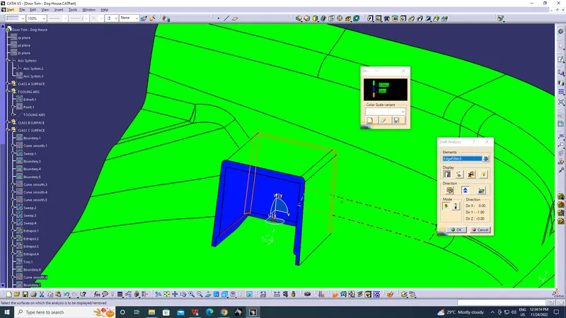
The draft analysis technique is used to analyze whether our part model created in CAD is manufacturable based on the draft condition applied. Here the part should get easily removed from the Mold. No parts can be ejected from the tool if it is having a straight 90-degree profile from its base surface. A small draft angle is provided to each and every area of the component in order to get easy removal of the component from the tool.
DOG HOUSE:
Dog HOuse is an engineering feature used in plastic trim design.Dog houses are used as supporting feature. The primary function of Dog House is to avoid SINKMARK.
STEP-1:
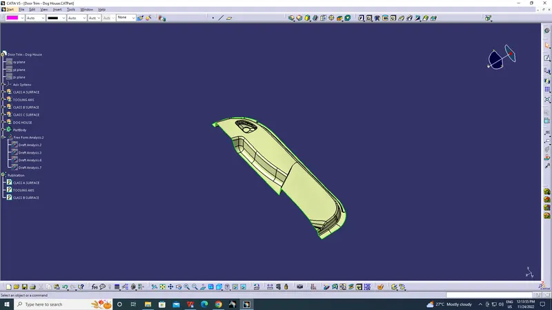
JOIN THE GIVEN CLASS A SURFACE WITH MERGING DISTANCE OF 0.1MM
STEP-2:
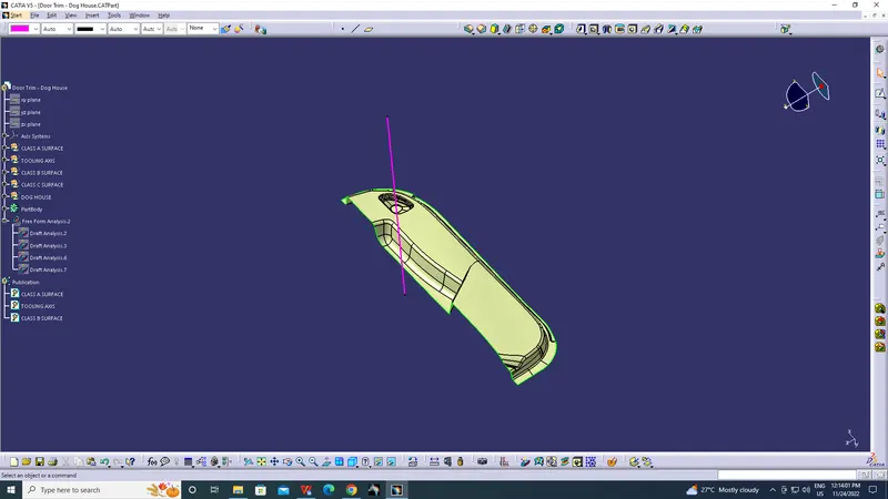
TOOLING AXIS CREATION
The component is viewed in all axes namely X,Y and Z.
It is determined that the X-axis will be the direction for the Tooling axis and a line is created Using the point and X-direction as direction of the line.
STEP-3:
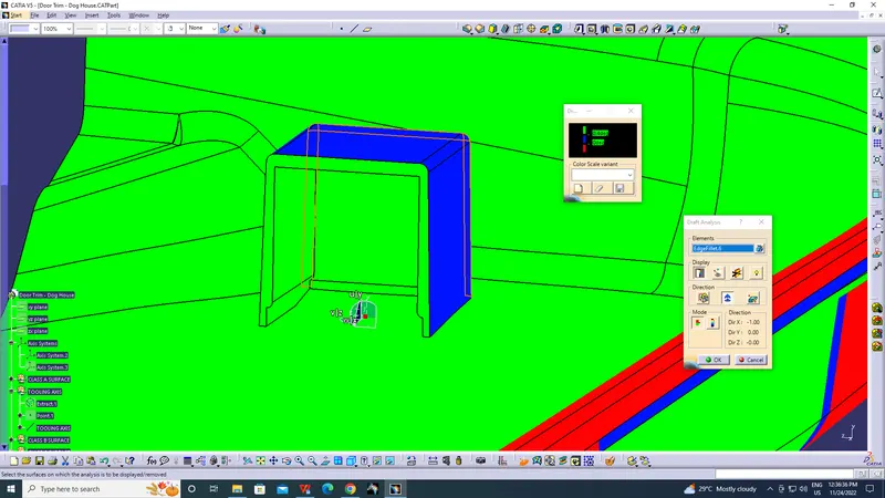
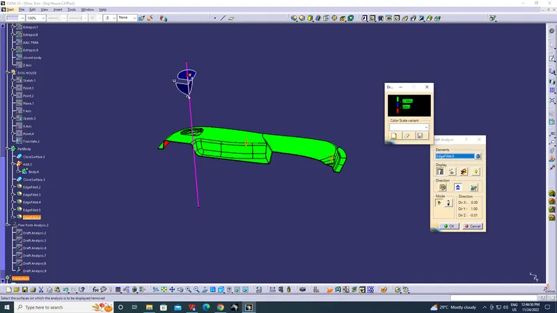
Draft analysis for the given CLASS-A surface
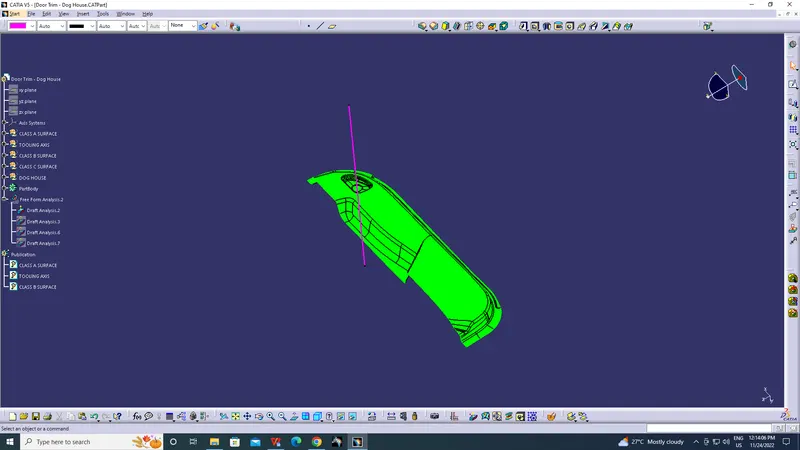
Change the view mode of the component to be in customized parameter mode and then select the shading mode as materials.
Then open the featured draft analysis tool from the insert menu.
Then click on use the compass to define the current drafting direction and then drag and align the compass on the Tooling axis.
Then lock the draft direction and perform draft analysis by clicking on the component.
The green colour shows the positive daft tooling direction and the given surface passes the draft analysis.
Click on the analyses under the running point to check the draft analysis on the individual faces. It shows how much draft on specific points when we move the cursor point.
STEP-4:
SURFACE-B CREATION
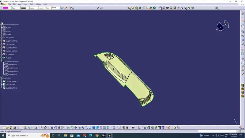
Offset the class-A surface to 3mm inward direction.
Rework on the patches and discontinuity of the offset surfaces using the features like multi-extract, Split, multi-section surfaces, extrapolate.
To ensure the continuity of the Class-B surfaces check the boundary command to find out the boundary.
Hence class-B surface creation is done.
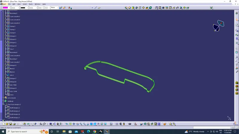
STEP-5:
SURFACE C CREATION:
Surface that joins class-A and class-B surfaces is class-C surface.
Class C is often specified for interior surfaces not readily visible, surfaces that will be covered by another part when assembled.
STEP-6:
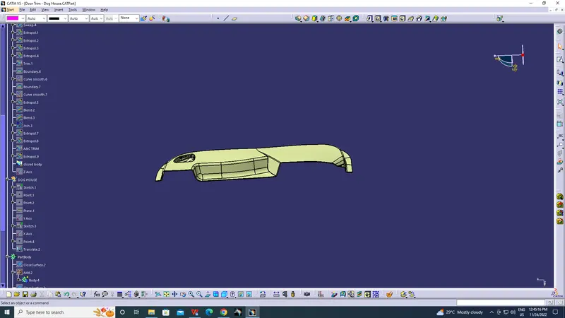
CLOSED SURFACE CREATION:
After creating Class C surface join A and C surface and finally trim with surface.
DESIGNING OF THE DOG HOUSE
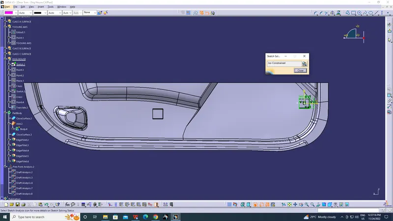
The dog house is an engineering feature used in the plastic trim design. Dog houses are used as supporting features. Sometimes other engineering features like snaps; locators, etc. are mounded on them to increase their strength.
- The dog house is mostly used in automotive plastic and its main purpose is to help to avoid sink marks and saver of wall thickness
There are many design factors considered in to design of a dog house:
Doghouse wall thickness at the intersection of the part wall ( C ) should be 40% or less than the main wall stock ( T ).
The height of ( B ) should be between 3.0 – 6.0 mm
- Extract the base of Class A Surface and offset it with a part thickness of 2.5 mm.
- Draw a sketch of the open rectangle and extrude the rectangle at some height of 30 mm.
- Close the upper surface face by offsetting the below-extracted surface and then after trimmed it.
applying part thickness as 2 mm. - Give the draft to the inside surface of 0.5 degrees.
- Now to create the C and B sections as shown in the design rules, offset the base surface between 3 to 6 mm.
CONCLUSION :
The Doghouse is created using prefect draft analysis.