Week 8 - Challenge 4 - Bumper
Aim:
To create a Bumper Plastic Component through a given Class A Surface and perform Draft Analysis on the final plastic component.
Objectives:
- To Create a Tooling Axis.
- To Create Class B and Class C surface.
- To Create a solid part using surface modelling.
- To Perform Draft Analysis of Class A surface and final plastic component.
TOOLING AXIS:
The Tooling Axis is the direction in which the mould travels. The mold is built in two separate piece named core and cavity.
Three methods for creation of a tooling axis:
- Tooling axis based on x,y,z direction.
- bisecting method.
- normal to the surface.
CLASS-A SURFACE:
It is aesthetic surface and the outer most surface which is visible to the cutomers.
CLASS-B SURFACE:
It is simply off-set of Class A surface and inner most part which is not visible to the customers.
CLASS-C SURFACE:
A surface that joins class-A and class-B surfaces is class-C surface(thickness).
Draft analysis:
The draft analysis technique is used to analyze whether our part model created in CAD is manufacturable based on the draft condition applied. Here the part should get easily removed from the Mold. No parts can be ejected from the tool if it is having a straight 90-degree profile from its base surface. A small draft angle is provided to each and every area of the component in order to get easy removal of the component from the tool.
BUMPER USES:
The purpose of bumpers is to reduce or absorbing shock and prevent physical damage to the front and rear of vehicles in low-speed crashes. By design, bumpers protect the hood, trunk, grille, fuel, exhaust, and cooling system.
MATERIAL USED IN BUMPER AND WHY IT IS USED?
- Acrylonitrile Butadiene Styrene (ABS) is a copolymer made by polymerizing styrene and acrylonitrile in the presence of polybutadiene. The styrene gives the plastic a shiny, impervious surface. The butadiene, a rubbery substance, provides resilience even at low temperatures. A variety of modifications can be made to improve impact resistance, toughness, and heat resistance.Plastic bumper fasteners and clips are widely popular nowadays as they are largely available in various head sizes and configurations. These are used for a wide variety of automotive applications such as window mechanisms, hood insulation, window rollers, cable tracks, and more. Plastic bumper fasteners increase design freedom, and are very impact-resistant.
- Some times industries may use ABS+PC blends for manufacture of Bumpers to follow up government norms. PC/ABS blends combine the advantages of both materials, with PC improving mechanical properties and heat resistance and ABS ensuring good surface quality and optimum workability. Even at low temperatures, PC/ABS blends offer high toughness.
STEP-1:
JOIN THE GIVEN CLASS A SURFACE WITH MERGING DISTANCE OF 0.1MM 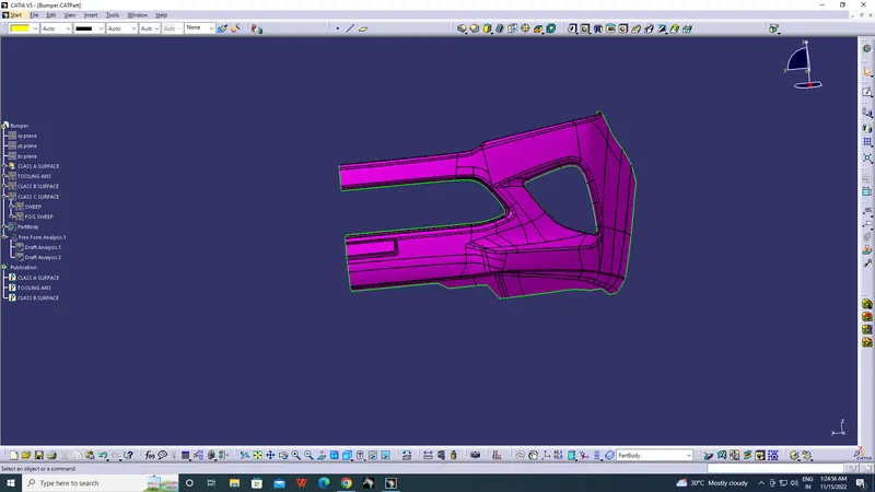
STEP-2:
TOOLING AXIS CREATION
-
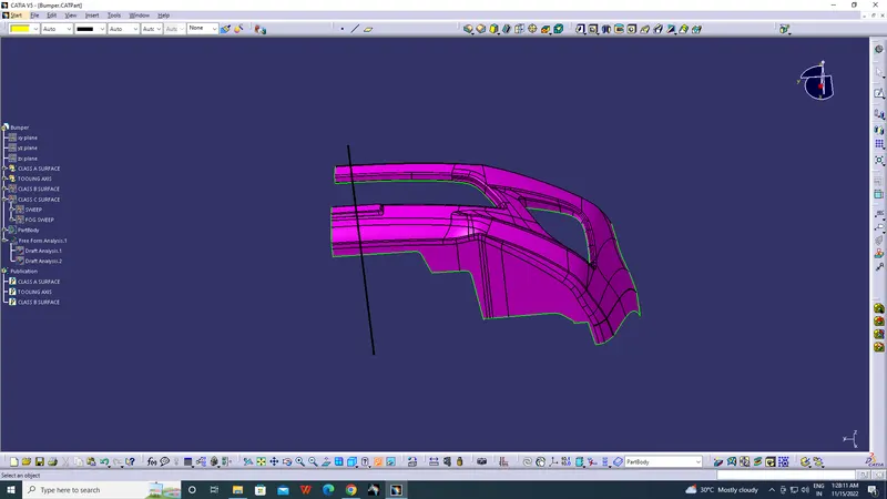
The component is viewed in all axes namely X,Y and Z.
-
It is determined that the X-axis will be the direction for the Tooling axis and a line is created Using the point and X-direction as direction of the line.
STEP-3:
Draft analysis for the given CLASS-A surface
- Change the view mode of the component to be in customized parameter mode and then select the shading mode as materials.
- Then open the featured draft analysis tool from the insert menu.
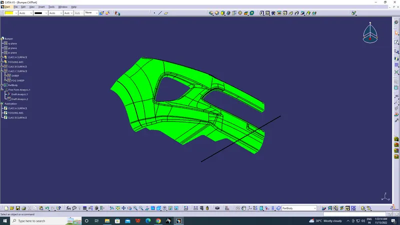
- Then click on use the compass to define the current drafting direction and then drag and align the compass on the Tooling axis.
- Then lock the draft direction and perform draft analysis by clicking on the component.
- The green colour shows the positive daft tooling direction and the given surface passes the draft analysis.
- Click on the analyses under the running point to check the draft analysis on the individual faces. It shows how much draft on specific points when we move the cursor point.
STEP-4:
SURFACE-B CREATION
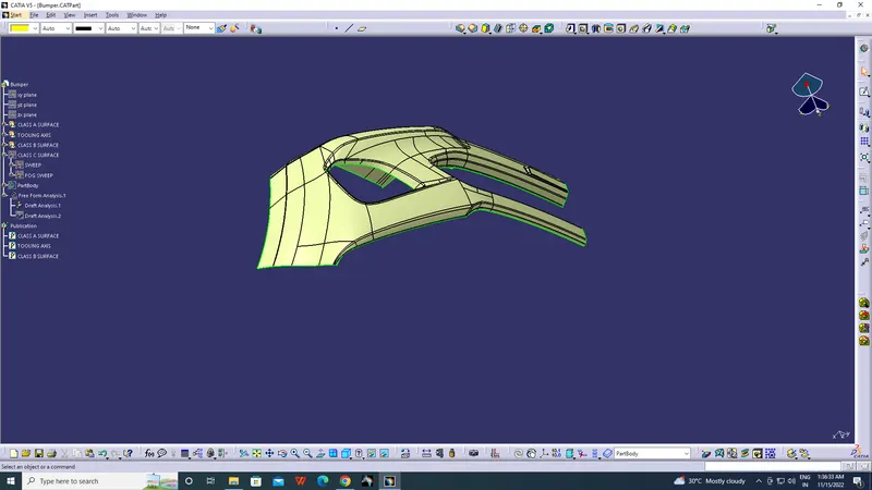
- Offset the class-A surface to 3mm inward direction.
- Rework on the patches and discontinuity of the offset surfaces using the features like multi-extract, Split, multi-section surfaces, extrapolate.
- To ensure the continuity of the Class-B surfaces check the boundary command to find out the boundary.
- Hence class-B surface creation is done.
STEP-5:
SURFACE C CREATION:
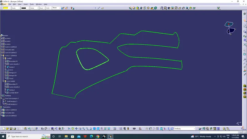
- Surface that joins class-A and class-B surfaces is class-C surface.
- Class C is often specified for interior surfaces not readily visible, surfaces that will be covered by another part when assembled.
- Since it is a complex class-A surface, we cannot simply create the class-A boundary curve and sweep it at one shot.
- Hence, we need to create smaller curves using multi-extract command and then create sweep of 90 degree with reference to the surface option.
- sweeps at the midportion of the bumper should have a 93 degree vaue to pass the draft analysis.
STEP-6:
Creating the Closed surface of Bumper
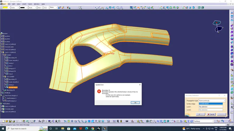
- First step is to join the CLASS-A surface with CLASS-C surface.
- Then Trim the Joined surface with CLASS-B surface to achieve the final Bumper surface.
STEP-7:
Draft analysis of the Final part body
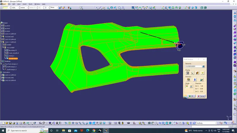
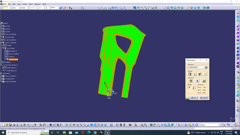
Same procedure for the draft analysis of CLASS-A surface is followed.
- Change the view mode to material shading
- Align the Compass with Tooling axis.
- Lock the draft direction and perform the Draft analysis.
STEP-6:
Use closed surface command to create the solid part.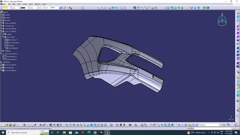
CONCLUSION:
The class-B and Class-C surfaces of Bumper using the given Class-A surface along with the tooling axis in the CATIA surface workbench.